
Turn on suggestions
Auto-suggest helps you quickly narrow down your search results by suggesting possible matches as you type.
Showing results for
Please log in to access translation
Turn on suggestions
Auto-suggest helps you quickly narrow down your search results by suggesting possible matches as you type.
Showing results for
Community Tip - Have a PTC product question you need answered fast? Chances are someone has asked it before. Learn about the community search. X
- Community
- Creo+ and Creo Parametric
- 3D Part & Assembly Design
- Use parameter from assembly in a part
Translate the entire conversation x
Please log in to access translation
Options
- Subscribe to RSS Feed
- Mark Topic as New
- Mark Topic as Read
- Float this Topic for Current User
- Bookmark
- Subscribe
- Mute
- Printer Friendly Page
Use parameter from assembly in a part
Oct 25, 2014
10:06 AM
- Mark as New
- Bookmark
- Subscribe
- Mute
- Subscribe to RSS Feed
- Permalink
- Notify Moderator
Please log in to access translation
Oct 25, 2014
10:06 AM
Use parameter from assembly in a part
I created a parameter in my assembly and now I want to be able to use the value from that parameter in on of my assembled parts. But I can't figure out how to link that parameter to my part.
This thread is inactive and closed by the PTC Community Management Team. If you would like to provide a reply and re-open this thread, please notify the moderator and reference the thread. You may also use "Start a topic" button to ask a new question. Please be sure to include what version of the PTC product you are using so another community member knowledgeable about your version may be able to assist.
Solved! Go to Solution.
Labels:
- Labels:
-
Assembly Design
ACCEPTED SOLUTION
Accepted Solutions
Oct 28, 2014
09:40 PM
- Mark as New
- Bookmark
- Subscribe
- Mute
- Subscribe to RSS Feed
- Permalink
- Notify Moderator
Please log in to access translation
Oct 28, 2014
09:40 PM
I thought of a way to do this.
In the assembly I activate the part and start a sketch. In the sketch I reference the two axis in my main assembly that is the pitch and draw a line between them. Then I put a reference dimension on it. Exit the sketch and then create a new "pitch" parameter and then setup a relation that sets the new "pitch" parameter in the part equal to the reference dimension.
Now when I change the pitch parameter in the assembly, the pitch parameter in the part updates!
Happy days.
27 REPLIES 27
Oct 25, 2014
12:43 PM
- Mark as New
- Bookmark
- Subscribe
- Mute
- Subscribe to RSS Feed
- Permalink
- Notify Moderator
Please log in to access translation
Oct 25, 2014
12:43 PM
I am no expert at creating cross part references but I do know of a few options depending on what you are trying to achieve.
1st of all, you can easily create external references by activating a component in the assembly and using assembly references in the currently active part. I don't know the limitations, but take a sketch, for instance, and create assembly references in the sketch. These work well and they create an external reference automatically.
2nd, consider a flexible model in the assembly (make flexible). You can change a part feature to some assembly level value. There are quite a few options when you do this.
3rd, you can use merge models in case you need some extensive external reference. Typical for tooling operations, but useful in some other cases.
Things to remember about external references is to know when the part level updates and how changes are rolled up at all levels. This is where I get squeamish about external references. The more complex the operation, the higher the likelihood of corruption.
Can you share more about what you wish to achieve to better match a method?
Oct 25, 2014
01:05 PM
- Mark as New
- Bookmark
- Subscribe
- Mute
- Subscribe to RSS Feed
- Permalink
- Notify Moderator
Please log in to access translation
Oct 25, 2014
01:05 PM
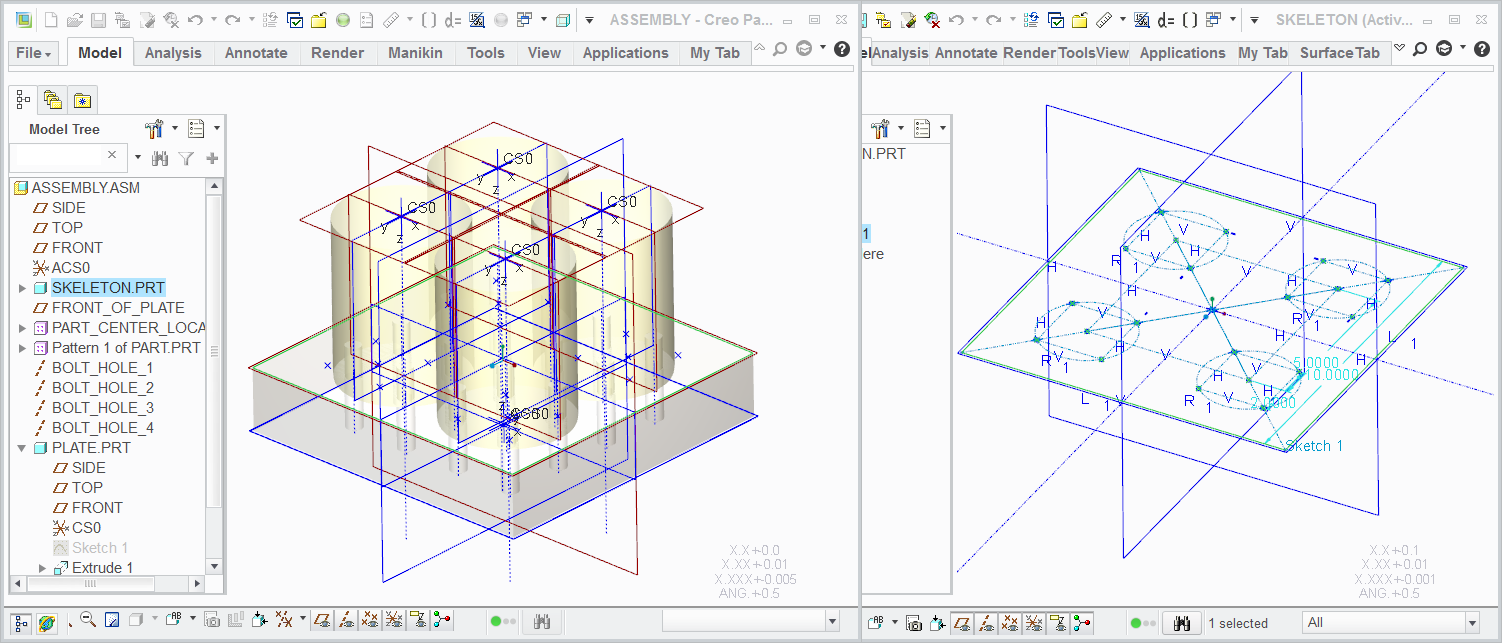
I've attached a simplified assembly of what I am working on. I am designing a mold.
If you look at the attached picture there are parts that get bolted to the plate. I created the holes in the part first and then used them as a reference to create the holes in the plate.
I created a parameter called pitch to define where the parts are located. Now I want to use this pitch parameter to pattern the bolt holes in the plate using a relation.
Hopefully this makes sense.
Oct 25, 2014
01:18 PM
- Mark as New
- Bookmark
- Subscribe
- Mute
- Subscribe to RSS Feed
- Permalink
- Notify Moderator
Please log in to access translation
Oct 25, 2014
01:18 PM
That shouldn't be hard. Let me try this before I put my foot in my mouth ...again.
Oct 25, 2014
01:38 PM
- Mark as New
- Bookmark
- Subscribe
- Mute
- Subscribe to RSS Feed
- Permalink
- Notify Moderator
Please log in to access translation
Oct 25, 2014
01:38 PM
So yes, you have already created external references for the bolt holes in the plate by defining the axes where the holes were placed in the plate. To copy the pattern, I simply did the same thing (patterned the pattern of holes using direction).
In the sample assembly, activate the plate; pattern the bolt pattern (show features in the model tree); use direction 1 and direction 2 and drag the dragger in the right direction; okay the pattern and now edit the pattern dimensions, direction 1 and enter "pitch" and let it save it as a relation; select the value for direction 2 and replace that with "pitch". regen and whallah! holes patterned in the part according to the assembly relation "pitch".
Of course, patterning a pattern is not always that successful, but in general, this is the right idea.
However, the inter relationship between the two parts can get messy. I had trouble just figuring out how you placed the original set. We can hack something like this together but when it comes to sustaining this design for years to come, it can really throw a user for a loop. I recommend using this method sparingly.
The idea is that you can build a huge top down design and have inter-dependencies out the whazoo. This is great for the thinking process in optimizing a design and not having to worry about every little detail. However, I highly recommend that before drawings and production planning, someone clean up these types of designs to make parts as independent as possible. This is my take on top down assembly but for the most part, making designs sustainable has always been a priority for me.
Oct 25, 2014
02:03 PM
- Mark as New
- Bookmark
- Subscribe
- Mute
- Subscribe to RSS Feed
- Permalink
- Notify Moderator
Please log in to access translation
Oct 25, 2014
02:03 PM
You know, sometimes you think you got it just to find an issue later. I just learned that the above method does in fact not create the d52=pitch relation but acts like it does.
So I did the same as you did for the hole pattern. Created a sketch with a datum point at the 4 axis locations. I used those points for a point pattern. Now it is associative but still not using the "pitch" reference, just a feature that is created in the assembly using the pitch reference.
There has to be a way to pass just the parameter to a lower level part. Hopefully someone will make this easier.
Oct 25, 2014
02:06 PM
- Mark as New
- Bookmark
- Subscribe
- Mute
- Subscribe to RSS Feed
- Permalink
- Notify Moderator
Please log in to access translation
Oct 25, 2014
02:06 PM
Thanks Antonius.
But, when I do this it doesn't maintain the relationship with the parameter pitch. So if I change the value of "pitch" it does not update the location of the holes in the plate. Maybe I did something wrong?
Oct 25, 2014
02:12 PM
- Mark as New
- Bookmark
- Subscribe
- Mute
- Subscribe to RSS Feed
- Permalink
- Notify Moderator
Please log in to access translation
Oct 25, 2014
02:12 PM
You can create parameter in any part/assembly/sekleton and use/call it in some part.
Trick is to know assemblys/parts session id but you can get that info in relations-show tab-Session id
then pick assy or part from which you want to "steal parameter".
Use that id in relations of part which is "stealing" parameter like X=PARAMETER_NAME:session id
I use this to change part numbering by changing assemblys number when im reusing some huge assemblys that need thir numbering changed.
Oct 25, 2014
02:22 PM
- Mark as New
- Bookmark
- Subscribe
- Mute
- Subscribe to RSS Feed
- Permalink
- Notify Moderator
Please log in to access translation
Oct 25, 2014
02:22 PM
Davor, session ID's are dynamic. Does this not risk unassociating this value?
Oct 25, 2014
02:24 PM
- Mark as New
- Bookmark
- Subscribe
- Mute
- Subscribe to RSS Feed
- Permalink
- Notify Moderator
Please log in to access translation
Oct 25, 2014
02:24 PM
Oddly enough I didnt have this problem. But gona have to check this on monday on those assemblys when i open few more unasociated parts/stuff.
Oct 25, 2014
02:36 PM
- Mark as New
- Bookmark
- Subscribe
- Mute
- Subscribe to RSS Feed
- Permalink
- Notify Moderator
Please log in to access translation
Oct 25, 2014
02:36 PM
When I erase the assembly from the current session, I get this at the part level...
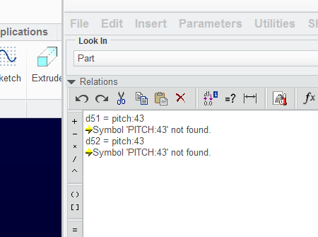
However, when I load a different assembly, and then reload this assembly, the session ID number heals itself.
Oct 25, 2014
02:30 PM
- Mark as New
- Bookmark
- Subscribe
- Mute
- Subscribe to RSS Feed
- Permalink
- Notify Moderator
Please log in to access translation
Oct 25, 2014
02:30 PM
Thanks Davor. I see that an error is generated in my original solution... but with the session ID of the assembly being 1, replace "pitch" with "pitch:1" when editing the dimensions. This writes the relation into the part's part level relation at d51=pitch:1 and d52=pitch:1. of course, I would prefer these relations at the feature level... and maybe even post regeneration.
Oct 25, 2014
02:50 PM
- Mark as New
- Bookmark
- Subscribe
- Mute
- Subscribe to RSS Feed
- Permalink
- Notify Moderator
Please log in to access translation
Oct 25, 2014
02:50 PM
Just to capture the conversation so far:
Oct 25, 2014
03:12 PM
- Mark as New
- Bookmark
- Subscribe
- Mute
- Subscribe to RSS Feed
- Permalink
- Notify Moderator
Please log in to access translation
Oct 25, 2014
03:12 PM
And to complete the conversation with top-down assemblies:
If you don't have the extension that does skeletons (advance assembly extension?) then you can still use this as a reference to help manage top-down assemblies.
The techniques above still apply with a few caveats.
Create a skeleton model (1 or more) and use this to define general interfaces. Sketches, datums, parameters, etc. that defines your general design intent. This is your sketchpad.
As you build associativity other than assembly constraints; use the skeleton model to build external relations. "pitch" for instance would be a skeleton parameter and could be used in a sketch to define how "pitch" was used.
You can still use the parameters directly using the session ID but you would use the session ID of the skeleton.
Now you have reduced the number or parts that can be inter-related to only 1 skeleton. A change in the skeleton should easily roll into the entire design. For more complicated designs, you can do the same with sub-assemblies. It can get quite comprehensive, but this level of planning is invaluable in a top-down design approach. Nothing worse than having an error and having no idea on how you need to trace the fault due to a very simple little tweak to the design.
This would be a simple but comprehensive skeleton for this design... a 3-dimension sketch to drive parts and assembly references.
Oct 26, 2014
06:03 AM
- Mark as New
- Bookmark
- Subscribe
- Mute
- Subscribe to RSS Feed
- Permalink
- Notify Moderator
Please log in to access translation
Oct 26, 2014
06:03 AM
Davor,
I would use the relation the other way round from the assembly.
X:sid=PARAMETER
with sid the session_id of your part. If the parameter in your part does not exist it will be created.
So you could open your part standalone and do some testing, in the assembly it will behave as intended.
Oct 26, 2014
03:30 PM
- Mark as New
- Bookmark
- Subscribe
- Mute
- Subscribe to RSS Feed
- Permalink
- Notify Moderator
Please log in to access translation
Oct 26, 2014
03:30 PM
This is a good thing to do since you can use the relations dialog to pass parameters forward.
In the example you would pass data up, and back again: The holes in the plate can manage the assembly pattern and the cylinder's hole pattern. However, the hole pattern would have to be passed downwards again from the plate to the cylinder via the assembly. It all does get rather messy in the end.
Somehow I expected the interface to be a little smarter about creating the parameter where it would have automatically added the session ID to the relation when replacing the value with an existing parameter. Rather, you simply get a quiet little message at the bottom of the screen about the symbol not being found, yet it takes on the value for the one it -did- find. This could easily be improved in code!
Oct 25, 2014
07:18 PM
- Mark as New
- Bookmark
- Subscribe
- Mute
- Subscribe to RSS Feed
- Permalink
- Notify Moderator
Please log in to access translation
Oct 25, 2014
07:18 PM
A safe method is to use Pro/Layout or Creo Notebook**. See http://help.ptc.com/creo_hc/creo30_pma_hc/usascii/index.html#page/pma/assembly/asm_three_sub/About_Notebooks.html
It lets you store common values in a single place that can be used at a variety of levels. It's part of Top Down Design methods.
**Not Creo Layout, which is entirely different from Pro/Layout.
Oct 25, 2014
07:42 PM
- Mark as New
- Bookmark
- Subscribe
- Mute
- Subscribe to RSS Feed
- Permalink
- Notify Moderator
Please log in to access translation
Oct 25, 2014
07:42 PM
Are notebooks included in core Creo?
Oct 25, 2014
11:29 PM
- Mark as New
- Bookmark
- Subscribe
- Mute
- Subscribe to RSS Feed
- Permalink
- Notify Moderator
Please log in to access translation
Oct 25, 2014
11:29 PM
Ask your sales guy.
Oct 26, 2014
03:58 AM
- Mark as New
- Bookmark
- Subscribe
- Mute
- Subscribe to RSS Feed
- Permalink
- Notify Moderator
Please log in to access translation
Oct 26, 2014
03:58 AM
Nope, its not.
Oct 26, 2014
04:55 AM
- Mark as New
- Bookmark
- Subscribe
- Mute
- Subscribe to RSS Feed
- Permalink
- Notify Moderator
Please log in to access translation
Oct 26, 2014
04:55 AM
How about using parts or subassembly as skeleton "replacement" just give them some material with close to 0 mass.
Oct 26, 2014
03:36 PM
- Mark as New
- Bookmark
- Subscribe
- Mute
- Subscribe to RSS Feed
- Permalink
- Notify Moderator
Please log in to access translation
Oct 26, 2014
03:36 PM
Skeletons appear to have a lot of "ghostly" attributes that the advanced assembly module makes use of. With core Creo, you have to make due. So yes, a part or assembly model with design intent (datum features/sketches/mechanism constraints for more complex ideas...) could be assembled in the sub/top assembly and referenced in a pseudo top-down development effort. You can even activate the mechanisms from the make-shift skeletons to drive assembly analysis. The idea is that you can give you entire design design constraints before you even begin to put mass to the project.
Oct 26, 2014
04:38 PM
- Mark as New
- Bookmark
- Subscribe
- Mute
- Subscribe to RSS Feed
- Permalink
- Notify Moderator
Please log in to access translation
Oct 26, 2014
04:38 PM
As I was explaining, the reason Pro/Layout or Creo Notebook is a better solution is because it can be used to create a basis in advance of any other parts or assemblies, and unlike skeletons, does not have any noticeable** regeneration overhead, particularly when used. Since they are independent of parts or assemblies, one can retrieve and independent item from an assembly, assured that all remain as coordinated as designed. They also do not affect layers in parts or assemblies where they are referenced; they don't have any that can. P/L or C/N also does not require retrieving or regenerating potentially complex models, and layouts cannot fail from geometry construction failures - they have no geometry that can fail. These characteristics makes them safer for sharing non-geometric information, such as parameters as the OP requested.
As an example of the effect of undesireable interdependence from using skeletons, when one aligns to a skeleton, there are no driving dimensions created in the model that the alignment is in, so there is no place to attach dimension specific changes, such as notes.
From the declared layout, only the value is driven; any dimension entity using that value is still wholly part of the detail part or assembly and can be customized with additional text specific to its use.
If, as the original poster requested, a single parameter was desired to be shared, the Layout or Notebook makes what was shared explicit, and in a way that is more easily documented than a relation with a session ID dependent value.
If the user has AAX, then they should have Notebook. If they are designing molds, they should have AAX.
Oct 26, 2014
05:01 PM
- Mark as New
- Bookmark
- Subscribe
- Mute
- Subscribe to RSS Feed
- Permalink
- Notify Moderator
Please log in to access translation
Oct 26, 2014
05:01 PM
Thanks for the overview of the layout/notebook, David. Alas... I am still a core Creo owner and have no plans to upgrade. However, in the investigation of finding out if I have notebook, it turns out somehwere there is a manufacturing lite extension in core Creo. That I'm going to have to investigate.
Obviously I am not familiar enough with the AAX terminology to understand exactly what is what. I use the term skeleton in a very loose sense. In general, I am not a proponent for a top-down assembly file structure going into production. Maybe it is possible to make this feasible for long term sustaining of a design. Without more insight, I wouldn't know. I haven't worked on anything complex enough to require this. However, I do have master parameters that I have to adhere to throughout my design process. Creating these pseudo sketleton models that eventually have all their dependencies removed has worked well for now.
Maybe need a new user trademark.. PoorMan's|Pro^tm to encompass core Creo Pro|WorkAround^tm for not having all the tools available.
Oct 29, 2014
05:14 AM
- Mark as New
- Bookmark
- Subscribe
- Mute
- Subscribe to RSS Feed
- Permalink
- Notify Moderator
Please log in to access translation
Oct 29, 2014
05:14 AM
lol PoorMan's|Pro^tm
I also don't have AAX, not even the TDO package that contains Pro/Mold and also AAX itself as well.
And guess what, with the point patterns I can tell I don't really need it.
I always avoid using SID's, and use regular geometry instead, cause SID's are pain to work with.
One thing that I do is to check how each of the parts and pseudo skeletons are dependent on each other is by RMB on the component in model tree --> Model --> Info and scroll right to the bottom of the info page.
Oct 26, 2014
08:08 PM
- Mark as New
- Bookmark
- Subscribe
- Mute
- Subscribe to RSS Feed
- Permalink
- Notify Moderator
Please log in to access translation
Oct 26, 2014
08:08 PM
I think we have AAX (advanced assemblies). I guess I will have to look into how to use notebook. For this job I think I'm going to create a pitch parameter in each part and manually adjust it for each file (god help the next person to work on this job 10 years from now).
Thanks for the help though. Would still think there would be a more straight forward way to tie a parameter from the main assembly to a part.
Oct 28, 2014
09:40 PM
- Mark as New
- Bookmark
- Subscribe
- Mute
- Subscribe to RSS Feed
- Permalink
- Notify Moderator
Please log in to access translation
Oct 28, 2014
09:40 PM
I thought of a way to do this.
In the assembly I activate the part and start a sketch. In the sketch I reference the two axis in my main assembly that is the pitch and draw a line between them. Then I put a reference dimension on it. Exit the sketch and then create a new "pitch" parameter and then setup a relation that sets the new "pitch" parameter in the part equal to the reference dimension.
Now when I change the pitch parameter in the assembly, the pitch parameter in the part updates!
Happy days.
Oct 28, 2014
11:45 PM
- Mark as New
- Bookmark
- Subscribe
- Mute
- Subscribe to RSS Feed
- Permalink
- Notify Moderator
Please log in to access translation
Oct 28, 2014
11:45 PM
That's kind of what I was getting at in the 6th post. This is an assembly reference rather than a parameter driven value. Just as valid, same considerations.


