Community Tip - You can Bookmark boards, posts or articles that you'd like to access again easily! X
- Community
- Creo+ and Creo Parametric
- 3D Part & Assembly Design
- Using 2D Axis Symmetry, Plane Strain, Plain Stress...
- Subscribe to RSS Feed
- Mark Topic as New
- Mark Topic as Read
- Float this Topic for Current User
- Bookmark
- Subscribe
- Mute
- Printer Friendly Page
Using 2D Axis Symmetry, Plane Strain, Plain Stress and Cyclic Symmetry Models in Pro/ENGINEER Mechanica
- Mark as New
- Bookmark
- Subscribe
- Mute
- Subscribe to RSS Feed
- Permalink
- Notify Moderator
Using 2D Axis Symmetry, Plane Strain, Plain Stress and Cyclic Symmetry Models in Pro/ENGINEER Mechanica
You can read the Product Focus here also authored by Tom Quaglia and you can also download the Enterprise portion of the newsletter authored by Michael Ferguson by clicking here.
| PTC Technical Specialists Newsletter - October 2010 |
Tip of the Month : Using 2D Axis Symmetry, Plane Strain, Plain Stress and Cyclic Symmetry Models in Pro/ENGINEER Mechanica |
|---|
Have you ever had to analyze a piece of rotating machinery or a complex revolved assembly and wished that you could have reduce the size of the Mechanica model - and the time associated with solving it? If you have symmetric loads and symmetric geometry, chances are more than good that you can use this to your advantage to reduce analysis run times greatly.
Although Mechanica takes advantage of multiple processors and has gained significant speed in the last few releases, like all software solutions, it will never be fast enough. If you intend on performing sensitivity studies or optimizations and you have an inefficient analysis, it will re-run numerous times over taking much more time than it could (or should).
Let’s look at an example including a rotating turbine impeller. To simplify the design, we are going to analyze it as a single part.
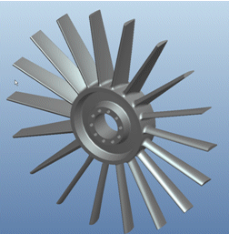
Turbine Impeller Design
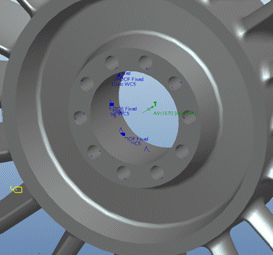
Centrifugal Load (Angular Velocity and Constraints)
In this model, we fix the inside of the holes in all 6 Degrees of Freedom and apply a Centrifugal Load at the center about the axis of the model. This Centrifugal load can be either an angular velocity or an angular acceleration. When we perform a Static Analysis (even though it is considered rotating), we get the following results:
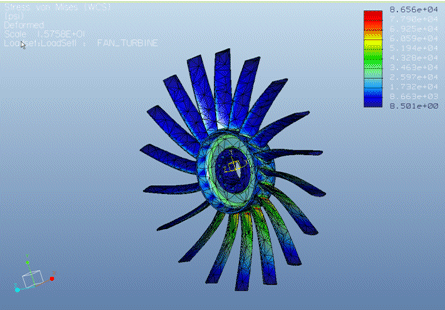
Static Analysis results showing Max VM Stress of full model (Runtime = 7mins)
Note that this same model can be run in considerably less time using Cyclic Symmetry constraints and only a small “pie” section of the model. Since this model has 18 equally spaced blades, we can cut a 20 degree section out of the model and analyze that. The only thing we need to add to the model will be a cyclic symmetry constraint.
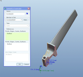
Cyclic Symmetry Constraint
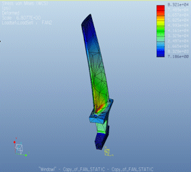
Same analysis as above (Runtime = 27 seconds)
Note that the results are within 3% of those from the full model which is usually within the convergence criteria of Mechanica and the runtime is 27 seconds as opposed to 7 minutes. This might not sound like a great deal of time difference but if an optimization needs to take place as many as 12 iterations are run, the time difference now becomes 6 minutes for the cyclic symmetry model as compared to 84 minutes for the full model.
Other examples where runtimes can be significantly reduced are with 2D Plane Stress and 2D Plain Strain models. Below is an example of a 3D solid model analyzed using symmetry constraints to reduce model size and runtime. The Large Deflection Analysis (LDA) took about 11 minutes to run mainly due to the 5 load intervals.
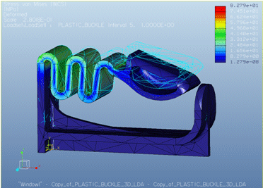
3D Solid Model Analysis using Large Deflection (Runtime = 11 minutes)
By running this same model as a 2D Plane Strain analysis, we have reduced the runtime to 18 seconds
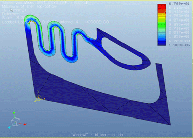
2D Plane Strain Analysis using Large Deflection (Runtime = 18 seconds)
One thing to note is that the geometry should be considered to be infinitely thick for an accurate 2D Plane Strain analysis. The difference in the results does lead us to believe that our assumption of infinite thickness is actually not valid for this particular geometry. Here we can use this 2D example for design iteration behavior but not final results.
Axis Symmetric geometry is when a 2D profile is revolved 360 degrees around an axis. The example below shows fairly intricate geometry interacting with contact surfaces. With revolved geometry, contact between surfaces can sometimes present a challenge. It is much easier to define an edge-to-edge contact if at all possible. This model gives us all of the accuracy of a full 3D assembly analysis without the wait.
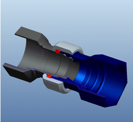
3D Coupler with Section Cut Out
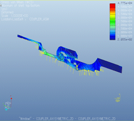
2D Axis Symmetric Analysis of Coupler
In the Axis Symmetric example, 3D loads, boundary conditions and contacts are applied to 2D geometry and are assumed to be acting along a 360 degree surface for each entity.
Whether it is using Cyclic Symmetry constraints, Plane Strain, Plain Stress, or Axis Symmetric models, Mechanica runtimes can be hugely impacted in a positive way to free up time for important design studies like Optimizations.
You can read the Product Focus here also authored by Tom Quaglia and you can also download the Enterprise portion of the newsletter authored by Michael Ferguson by clicking here.
This thread is inactive and closed by the PTC Community Management Team. If you would like to provide a reply and re-open this thread, please notify the moderator and reference the thread. You may also use "Start a topic" button to ask a new question. Please be sure to include what version of the PTC product you are using so another community member knowledgeable about your version may be able to assist.


