1-Visitor
October 20, 2014
Question

Wiring Harness Layout Drawing

  • October 20, 2014
  • 1 reply
  • 8442 views

Good morning,

One of our users has asked me the best way to achieve this drawing using Wildfire 4:

wiring_diagram.png

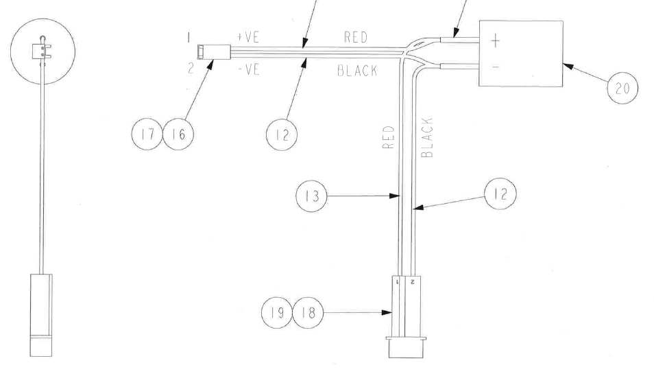
Ideally, he would like it to be a sub-assembly that he can use in the main assembly, but that he can also use to create a parametric drawing of this nature.

He is able to create the drawing as shown, but I am not convinced it is nearly as parametric as we would wish. Furthermore, the sub-assembly is this shape, so he cannot use it in the main assembly.

A BOM table showing wire lengths would be nice, too.

I know there are ways of making things fit, such as flexibility, simplified reps, etc., but I am interested in knowing what represents best practice.

We do have the cabling module, but, as many of you will be aware, it is as friendly as a cornered rat, so we would like to steer clear if at all possible!

Even if we do create something like this sub-assembly in Cabling, is it then easy to create this kind of drawing?

I look forward to your advice.

WF4, M220

Thanks,

John


This thread is inactive and closed by the PTC Community Management Team. If you would like to provide a reply and re-open this thread, please notify the moderator and reference the thread. You may also use "Start a topic" button to ask a new question. Please be sure to include what version of the PTC product you are using so another community member knowledgeable about your version may be able to assist.

1 reply

1-Visitor
October 20, 2014

John,

is this the Flat harness model, created with reference to the actual 3D harness part that fits into the top assembly?

Something in your description gives me the idea, this model might have been actually designed this way as a harness part in assembly mode - which would explain why you are obviously not very convinced about the functionality.

For a flat harness, creating this kind of drawing does not seem to be much of an effort and adding BOM tables with wire lengths is a usual procedure (you will need the Pro/REPORT option, like for any repeat region)

Or is it the thick display (instead of the schematic line display) that you are missing?

Gunter

JWayman1-VisitorAuthor
1-Visitor
October 20, 2014

Gunter,

Thank you.

Yes, this model has been created flat, as you see it in the drawing. It is pretty well useless for use in the 3D assembly, in which it would be curved in 3 dimensions.

I have, in the past, briefly done battle with Pro/Cabling in WF4. I think it is generally considered to be much inferior to the same module in later versions. That is certainly something to look forward to...

I wondered whether anyone had a nifty way to create a flat harness drawing from a sub-assembly model that actually fits the assembly! Without recourse to Pro/Cabling, that is.


John

1-Visitor
October 22, 2014

Hi John,

I agree that cabling is not the easiest module.

Correcting mistakes in the design could have been a pain in Wildfire 4.0 and before. Plus it was easy to make mistakes. So experience made a real difference in this module.

The correction mechnisms may have not improved much in Creo, but the chance to make mistakes has been significantly reduced with the current workflow. Most pain points currently, are about dealing with legacy cabling assemblies.

But even with the old cersion, thinking of designing the flat harness alone gives me the creep!

I'd rather redo the complete cabling and start all over again with the flat harness, one hand tied to my back, than manually creating a flat harness based on the 3D cabling. I am really curious whether somebody tried this - well, someone without the cabling mode would probably have to...

I really recommend you take another look, because this is exactly what cabling/harness MFG are made for.

Gunter