
Turn on suggestions
Auto-suggest helps you quickly narrow down your search results by suggesting possible matches as you type.
Showing results for
Please log in to access translation
Turn on suggestions
Auto-suggest helps you quickly narrow down your search results by suggesting possible matches as you type.
Showing results for
Community Tip - You can Bookmark boards, posts or articles that you'd like to access again easily! X
- Community
- Creo+ and Creo Parametric
- 3D Part & Assembly Design
- model/assembly parameter as variable in a optimisa...
Translate the entire conversation x
Please log in to access translation
Options
- Subscribe to RSS Feed
- Mark Topic as New
- Mark Topic as Read
- Float this Topic for Current User
- Bookmark
- Subscribe
- Mute
- Printer Friendly Page
model/assembly parameter as variable in a optimisation study
Feb 10, 2016
08:09 AM
- Mark as New
- Bookmark
- Subscribe
- Mute
- Subscribe to RSS Feed
- Permalink
- Notify Moderator
Please log in to access translation
Feb 10, 2016
08:09 AM
model/assembly parameter as variable in a optimisation study
Hello to all!
I am new on the forum and also quite new as a Simulate user, so please be patient with my questions... 
I am trying to solve a problem with a snap-fit, where I have a given geometry and I would like to calculate required retraction force.
This is the way I tried:
The model is constrained, material defined,... then I defined the retraction force as a parameter (relation input: FORCE=12) and defined the load as Dir Vector&Magnitude (x=0,y=0,z=1, Mag=FORCE)
Also I defined custom measure - deflection (measuring distance on a point on a snap). This way I can observe when the snap won't hold any more.
Is it possible to define the optimisation analysis as deflection as design limit (deflection>0.8) and FORCE as variable?
I tried, but I always get next error: "Error updating parameters: Cannot perform this operation for this case.
** Warning: Unable to recover from invalid design point
for the following parameter values: FORCE......"
Is this kind of optimisation possible or how do you suggest to solve my problem?
Many thanks in advance.
Best regards,
Franci
This thread is inactive and closed by the PTC Community Management Team. If you would like to provide a reply and re-open this thread, please notify the moderator and reference the thread. You may also use "Start a topic" button to ask a new question. Please be sure to include what version of the PTC product you are using so another community member knowledgeable about your version may be able to assist.
Solved! Go to Solution.
Labels:
- Labels:
-
2D Drawing
ACCEPTED SOLUTION
Accepted Solutions
Feb 10, 2016
10:44 AM
- Mark as New
- Bookmark
- Subscribe
- Mute
- Subscribe to RSS Feed
- Permalink
- Notify Moderator
Please log in to access translation
Feb 10, 2016
10:44 AM
Franci
Without knowing what your model looks like a general tip:
Normally for such a case you would use a prescribed displacement to a surface of the part that is supposed to move away from the snap and define a measure determining the reaction force required to achieve this displacement.
The graph results for this measure would show you the required force.
This analysis would of course require; Contact (for the snap connection) and large deformations, as well as results for a lot of output steps.
If you would post your model, somebody here is likely to complete it for you. You require an advanced simulate license for this.
Erik
5 REPLIES 5
Feb 10, 2016
10:44 AM
- Mark as New
- Bookmark
- Subscribe
- Mute
- Subscribe to RSS Feed
- Permalink
- Notify Moderator
Please log in to access translation
Feb 10, 2016
10:44 AM
Franci
Without knowing what your model looks like a general tip:
Normally for such a case you would use a prescribed displacement to a surface of the part that is supposed to move away from the snap and define a measure determining the reaction force required to achieve this displacement.
The graph results for this measure would show you the required force.
This analysis would of course require; Contact (for the snap connection) and large deformations, as well as results for a lot of output steps.
If you would post your model, somebody here is likely to complete it for you. You require an advanced simulate license for this.
Erik
Feb 11, 2016
09:03 AM
- Mark as New
- Bookmark
- Subscribe
- Mute
- Subscribe to RSS Feed
- Permalink
- Notify Moderator
Please log in to access translation
Feb 11, 2016
09:03 AM
Hi Erik,
I tried to solve the problem as you proposed and it works!
Many thanks for the great tip!
BR, Franci
Feb 12, 2016
08:47 AM
- Mark as New
- Bookmark
- Subscribe
- Mute
- Subscribe to RSS Feed
- Permalink
- Notify Moderator
Please log in to access translation
Feb 12, 2016
08:47 AM
Hi again.
I've found another problem.
I tried to solve the problem as Erik proposed and it worked. But now when I am trying to reproduce the force with different approach, I don't get the same results.
Let me explain.
Before I've got the tip from Erik, I tried to do the following thing:
Link to parts (creo simulate 3.0 M020): http://jmp.sh/v/OvhWaJoROXe6ogrPOgNZ
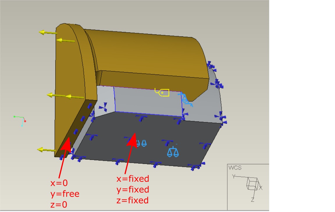
I constrained the "grey" part and the snapping part as shown in the picture. Then I apllied the force on the snap part (and place some barrier to prevent the snap from moving on into empty space). I've created a measure to see when the tip of the snap will be high enough to disassemble. Nothing good came out of this approach.
With the Erik's approach I managed to compute the force needed to disassemble the snap.
Now, when I know the force, I've tried to insert it into my approach and see what happens. I expected all the measures to be the same (snap tip height, resultant at constraint)...
But they are not!
Why not? Am I doing something wrong?
I am asking for your help again...
Many thanks in advance,
Franci
Feb 12, 2016
09:13 AM
- Mark as New
- Bookmark
- Subscribe
- Mute
- Subscribe to RSS Feed
- Permalink
- Notify Moderator
Please log in to access translation
Feb 12, 2016
09:13 AM
Franci,
In my experience such an analysis will never work using a force, because the software cannot establish equilibrium (either one of the parts is still behind the snap, or it is 1000000 mm beyond the snap. The same thing happens in the following movie. You have to do it using a prescribed displacement (in any FE software) Video Link : 6702
Furthermore: adding a (tiny) round on the grey part, and the accompanying contact interfaces would make your analysis a bit more elegant.
Also I do not like your constraints (too rigid), but see the challenge you've had with the cutout (it is not true symmetry).
Erik
Feb 15, 2016
01:20 AM
- Mark as New
- Bookmark
- Subscribe
- Mute
- Subscribe to RSS Feed
- Permalink
- Notify Moderator
Please log in to access translation
Feb 15, 2016
01:20 AM
Erik,
Now I see, why the "force approach" is not good.
I set up the constraints that way because I presume all deformation to happen in snap. The grey part is presumed to be rigid. And yes, there is not true symmetry, so that is why I added "manual" constrains to prevent movement in undesired directions.
I thank you for all your answers and explanations. I really appreciate it.
Best regards,
Franci


