
Turn on suggestions
Auto-suggest helps you quickly narrow down your search results by suggesting possible matches as you type.
Showing results for
Please log in to access translation
Turn on suggestions
Auto-suggest helps you quickly narrow down your search results by suggesting possible matches as you type.
Showing results for
Community Tip - New to the community? Learn how to post a question and get help from PTC and industry experts! X
- Community
- Creo+ and Creo Parametric
- 3D Part & Assembly Design
- poor mirror tool in Pro/Engineer
Translate the entire conversation x
Please log in to access translation
Options
- Subscribe to RSS Feed
- Mark Topic as New
- Mark Topic as Read
- Float this Topic for Current User
- Bookmark
- Subscribe
- Mute
- Printer Friendly Page
poor mirror tool in Pro/Engineer
Nov 17, 2013
06:11 AM
- Mark as New
- Bookmark
- Subscribe
- Mute
- Subscribe to RSS Feed
- Permalink
- Notify Moderator
Please log in to access translation
Nov 17, 2013
06:11 AM
poor mirror tool in Pro/Engineer
why does no one talk about a very weak mirror tool in Pro/Engineer?
cannot add features to current mirror feature.?cannot replace features in current mirror feature?
poor..so poor....
This thread is inactive and closed by the PTC Community Management Team. If you would like to provide a reply and re-open this thread, please notify the moderator and reference the thread. You may also use "Start a topic" button to ask a new question. Please be sure to include what version of the PTC product you are using so another community member knowledgeable about your version may be able to assist.
Labels:
- Labels:
-
General
20 REPLIES 20
Nov 17, 2013
05:57 PM
- Mark as New
- Bookmark
- Subscribe
- Mute
- Subscribe to RSS Feed
- Permalink
- Notify Moderator
Please log in to access translation
Nov 17, 2013
05:57 PM
We do talk about it... and even report it. And it works "as expected" 
Mirrored and even patterned features places early in the process with many later dependencies is really scary. Something to be avoided if at all possible. Sometimes for productivity's sake, you just have to find another way or backtrack in your design process. Wouldn't be the only limitation that forces me to do this.
I have a bad habit of putting 3 of the same design "thoughts" along a primary plane each with their own "center reference plane". Once I decide on the version I want, I have to go and re-relate all the features to the temporary plane back to the primary to center the part again. of course, I can simply change the plane's offset to 0 but that would be messy. As long as I've worked in this game, I pretty much got use to having to back-track at some point. Fortunately... it is always easier the second time - okay, usually.
Nov 18, 2013
10:40 AM
- Mark as New
- Bookmark
- Subscribe
- Mute
- Subscribe to RSS Feed
- Permalink
- Notify Moderator
Please log in to access translation
Nov 18, 2013
10:40 AM
I can relate. Had a failure recently due to the face that Pro/E cuts cylinderes into 1/2 cylinders, and the original feature to be mirrored referenced that 1/2 cylinder, which was different on the other side, and so it failed. This is a glitch that has plagued Pro/E since the beginning, and it's WAY past time they fixed it. What you can do is build everything off of planes such that no part of the part goes into the negative X, Y, or Z. I had to do that to fix a model once.
Nov 18, 2013
11:19 AM
- Mark as New
- Bookmark
- Subscribe
- Mute
- Subscribe to RSS Feed
- Permalink
- Notify Moderator
Please log in to access translation
Nov 18, 2013
11:19 AM
While PTC could do a better job hiding the problem, they really do have to split cylinders in order for them to have ends. Every surface requires a minimum of two edges so that a geometry bridge can be built across them. If the ends of cylinders were not two semi-circles, no ends could be generated; and since they have two semi-circles, the sides of the cylinders are also divided.
It results in patterns needing to reference the axis of a cylinder rather than a cylinder surface if they go more than half-way around
The math part is this: To evaluate a point on a surface one needs to move along the edges of the surface from 0 to 100% and create lines / splines between each evaluation point (44% for example.) If there is only one edge, then the line/spline would have only one end. Because the edges are divided into two pieces so that the end face can have two edges, and those edges are shared between the ends and the sides, the sides are also divided so that each edge has two faces attached to it. In all, a cylinder has 4 edges and four faces.
PTC could have written special purpose code that dealt exclusively with cylinders, but that would mean exception handling for all geometry that referenced cylinders.
The reason that's not a good idea is this: To generate the sides of the cylinder there has to be a 0% location and a 100% location, say at 0 degrees and 360 degrees. One is still left with a split at the 0/360 degree point- a start edge and a coincident end edge that are referenced by only one surface. In most solid modeling it is a rule that each edge must have two and only two surfaces that reference it. Here you would have two edges referenced by only one surface.
PTC can either write a bunch of software to deal with this exceptional case, or divide circles into two parts and have no exceptions.
Nov 18, 2013
12:14 PM
- Mark as New
- Bookmark
- Subscribe
- Mute
- Subscribe to RSS Feed
- Permalink
- Notify Moderator
Please log in to access translation
Nov 18, 2013
12:14 PM
nice information gained by me here....if someone could just raise the issue of weak MIRROR tool at the techincal commitee meeting.
Atleas the mirror tool should be able to add and replace features.I Hate to say this..but Solidworks does it nicely.
Nov 19, 2013
01:50 PM
- Mark as New
- Bookmark
- Subscribe
- Mute
- Subscribe to RSS Feed
- Permalink
- Notify Moderator
Please log in to access translation
Nov 19, 2013
01:50 PM
I'm not getting that. SW doesn't seem to have that issue, and you can take the 2 halves of a cylinder as surfaces and merge them. All I can say is that it causes a lot of failures that it shouldn't.
In AutoCAD, when they first got 3D (boolean, anyways), they recommended that no part of the geometry went into negative X, Y, or Z. I've taken and recreated geometry that failed, completely in positive space, and it fixed it.
Is that what the cure will have to be?
Sorry, still not buying the math thing, maybe it's just me.
Nov 19, 2013
02:09 PM
- Mark as New
- Bookmark
- Subscribe
- Mute
- Subscribe to RSS Feed
- Permalink
- Notify Moderator
Please log in to access translation
Nov 19, 2013
02:09 PM
You are not alone, Frank. A cylinder is a contiguous surface but mathematically, it can be a curved face of 360 degrees. The end and the beginning are in essence the same point in space. It can still be considered 2 points, no different than if two semi-cylindrical features share the same point. Fact is, PTC has always done it this way and always will continue to do it this way.
What disturbs me is that the axis doesn't have a direction. One should know which way a cylinder is mapped. Pro/E has always, to the best of my knowledge, considered the direction based on the right hand rule based on where the axis is picked. And we have the option to reverse that. I would much rather have an axis that works similarly to the planes that have a plus and minus side. Even there, the older Mate & Align was a stronger argument than the current Coincident which can flip at any time.
We need not be math majors to understand our CAD. We need a consistent platform so we can get the job done. The semi-cylinders of Pro/E is often a limitation rather than an aid. It would be a boon to make this coding decision -transparent- to the user. I'm not holding my breath.
Nov 19, 2013
03:12 PM
- Mark as New
- Bookmark
- Subscribe
- Mute
- Subscribe to RSS Feed
- Permalink
- Notify Moderator
Please log in to access translation
Nov 19, 2013
03:12 PM
I don't know or care about the math involved, I know I get failures because the software cuts cylinders in half. It needs fixing. I agree with Antonius about it being limitations that need fixing, however they do it. I shouldn't have to write the software, just use it......
As far as deleting the original half and the feature failing, of course it will fail, the merge is a child of the parent. I have yet to test and see if copying the 2 halves (surfaces), merging them, then referencing THAT instead will prevent the failures.
Pro/WORKAROUND and Pro/FANITY are by neccessity my most used modules....... 
Nov 19, 2013
03:41 PM
- Mark as New
- Bookmark
- Subscribe
- Mute
- Subscribe to RSS Feed
- Permalink
- Notify Moderator
Please log in to access translation
Nov 19, 2013
03:41 PM
Tom, could you please test the axis pattern feature with both halves of a cylinder or a sphere merged together? As Frank has suggested?
You might already have a model with this issue. I remember seeing one of your vids, where you've had a dimple that just wouldn't pattern any other way than using Geometry Pattern, because the dimple was made of two halves also. Geom Patterns are new in Creo 1.0 as far as I remember.
I know it is too much of a workaround, but I'm also wondering if this is gonna work. I doubt it.
Nov 19, 2013
04:04 PM
- Mark as New
- Bookmark
- Subscribe
- Mute
- Subscribe to RSS Feed
- Permalink
- Notify Moderator
Please log in to access translation
Nov 19, 2013
04:04 PM
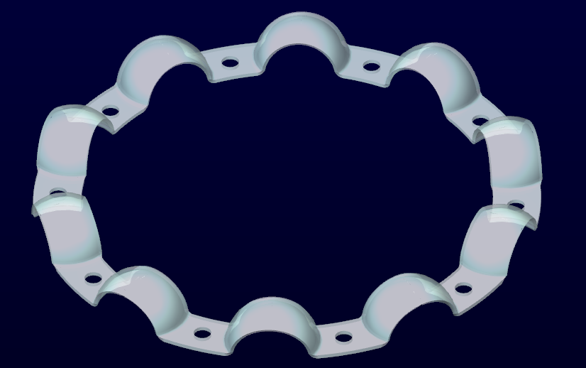
That was a bearing cage that I was working with, and it is this model that I submitted to PTC support. It worked in the version I created them in but later versions caused it to fail so I could not edit the part any longer. It really didn't matter what I did, even in the version I originally created it in. I just held my tongue right and it worked and I left it there. But in the later version, it displayed the same problem as before.
The two cylinder halves are recognized as a quilt. That too is internal. You can see this by subsequent operations where actions that involve both surfaces get acted upon. You also see this when it comes to solidifying an enclosed surface boundary when merging other faces. There is no reason to merge these separately.
This is where I brought this up before:
Cannot reference pattern a merge feature
Nov 19, 2013
04:24 PM
- Mark as New
- Bookmark
- Subscribe
- Mute
- Subscribe to RSS Feed
- Permalink
- Notify Moderator
Please log in to access translation
Nov 19, 2013
04:24 PM
This is Creo 2.0 M040 and how it differentiates a single cylinder from merged 1/2 cylinders manually merged. There is a difference in the Intent edge.
http://www.youtube.com/watch?v=_kDX42a93V0
...not sure why the uploaded video failed.
Nov 19, 2013
04:35 PM
- Mark as New
- Bookmark
- Subscribe
- Mute
- Subscribe to RSS Feed
- Permalink
- Notify Moderator
Please log in to access translation
Nov 19, 2013
04:35 PM
Ah, yes. I just don't really get why it fails. Really, I've to admit. I don't.
It's pretty bad that mirror feature, some of these strange pattern features, and some of the other odd features like component merge cannot be edited, but always have to be recreated.
It needs some sort of a mid-player like a skeleton model, or something that can simply be replaced as a whole if things go wrong.
I guess, lucky me I only have to deal with simple hole patterns, and mirrored hole features.
EDIT: Youtube says the video is private.
Nov 19, 2013
05:09 PM
- Mark as New
- Bookmark
- Subscribe
- Mute
- Subscribe to RSS Feed
- Permalink
- Notify Moderator
Please log in to access translation
Nov 19, 2013
05:09 PM
...
EDIT: Youtube says the video is private.
My Bad! 
Nov 19, 2013
02:50 PM
- Mark as New
- Bookmark
- Subscribe
- Mute
- Subscribe to RSS Feed
- Permalink
- Notify Moderator
Please log in to access translation
Nov 19, 2013
02:50 PM
Merging the surfaces simply hides the seams - they are still there. How can you tell for certain? Try to delete the original surfaces and keep just the result. (PTC could still hide copies to make this appear to work, but they are still there.)
Buy the math or not, if you understand how the software works without regard to how it should work or how other software appears to work, you'll have fewer problems and get answers more successfully. It's like any other sort of work. It would be nice to weld two pieces of wood together with a torch, but understanding what wood and a torch are like suggests looking elsewhere for a solution.
Antonius - the goal should be making this sort of decision completely opaque to the user; the user should have no need to know if it is done by splines, bezier curves, b-splines, t-splines, or strict geometric construction. It is that the results of the underlying decision are visible that causes problems. I agree and would like to worry less about units, accuracy, tiny edges, and large assembly management. It will, no doubt, be addressed in the -next- revision.
Nov 19, 2013
03:12 PM
- Mark as New
- Bookmark
- Subscribe
- Mute
- Subscribe to RSS Feed
- Permalink
- Notify Moderator
Please log in to access translation
Nov 19, 2013
03:12 PM
I really don't want to know the math behind it. I want a user interface that understands a cylinder as a 360 degree contiguous surface. When I drag a datum tag attachment over the cylinder's surface, I want to be able to drag the attachment anyplace on the full cylinder, not just half of it, and I certainly don't want to redefine the attachment because every cylinder is only 2 half-cylinders. This is not a good user interface no matter how you look at it.
Similarly with chains along the diametrical edge of a cylinder; I want that edge to be a value of 0 to 1, not just half of it, but the full circumference. For -my- practical purposes, this is the interface I am use to and -should- expect. I understand the fact that there will be a zero... I can live with that and i can manipulate that. But only having 1/2 a cylinder? No, this is something us Pro/E gurus have simply learned, and there really is no rhyme or reason that justifies disturbing the user with it.
We are not talking about all the other quirks here because then there are a lot of non-transparent things happening. In this instance, it is just the fact that a cylinder is not a mathematical definition of a cylinder within Pro/E. Actually, I think we've gone way off topic, but the very fact that this is being interpreted the way by the software, it is likely the at the very heart of the OP. I have -very- similar issues with patterns that only fail a -few- instances at only the 180 degree mark. one of which will be fixed in M090 as it was told to me.
We can go on and on, but when differentiating other CAD systems and even standard conversion protocols, you will find that Pro/E's method is -highly- unconventional at the user level.
Nov 19, 2013
04:57 PM
- Mark as New
- Bookmark
- Subscribe
- Mute
- Subscribe to RSS Feed
- Permalink
- Notify Moderator
Please log in to access translation
Nov 19, 2013
04:57 PM
Dirty Harry said " A man's -got- to know his limitations" at least the limitations of the software he uses.
Even if there was only a split at 0/360, it would still be a split and features crossing the split would still be prone to failure.
If that is happening, the location of the split can be changed by dividing the original circle into two or more segments. The divide can be 0-180 or 12-278.435. That way the split can be set to avoid conflict with other features.
Nov 19, 2013
05:10 PM
- Mark as New
- Bookmark
- Subscribe
- Mute
- Subscribe to RSS Feed
- Permalink
- Notify Moderator
Please log in to access translation
Nov 19, 2013
05:10 PM
I think we just went 360 
Nov 25, 2013
08:58 AM
- Mark as New
- Bookmark
- Subscribe
- Mute
- Subscribe to RSS Feed
- Permalink
- Notify Moderator
Please log in to access translation
Nov 25, 2013
08:58 AM
Qutoe from David 'If the ends of cylinders were not two semi-circles, no ends could be generated; and since they have two semi-circles, the sides of the cylinders are also divided.'
Either I completely misunderstand the words, or this is not correct as such.
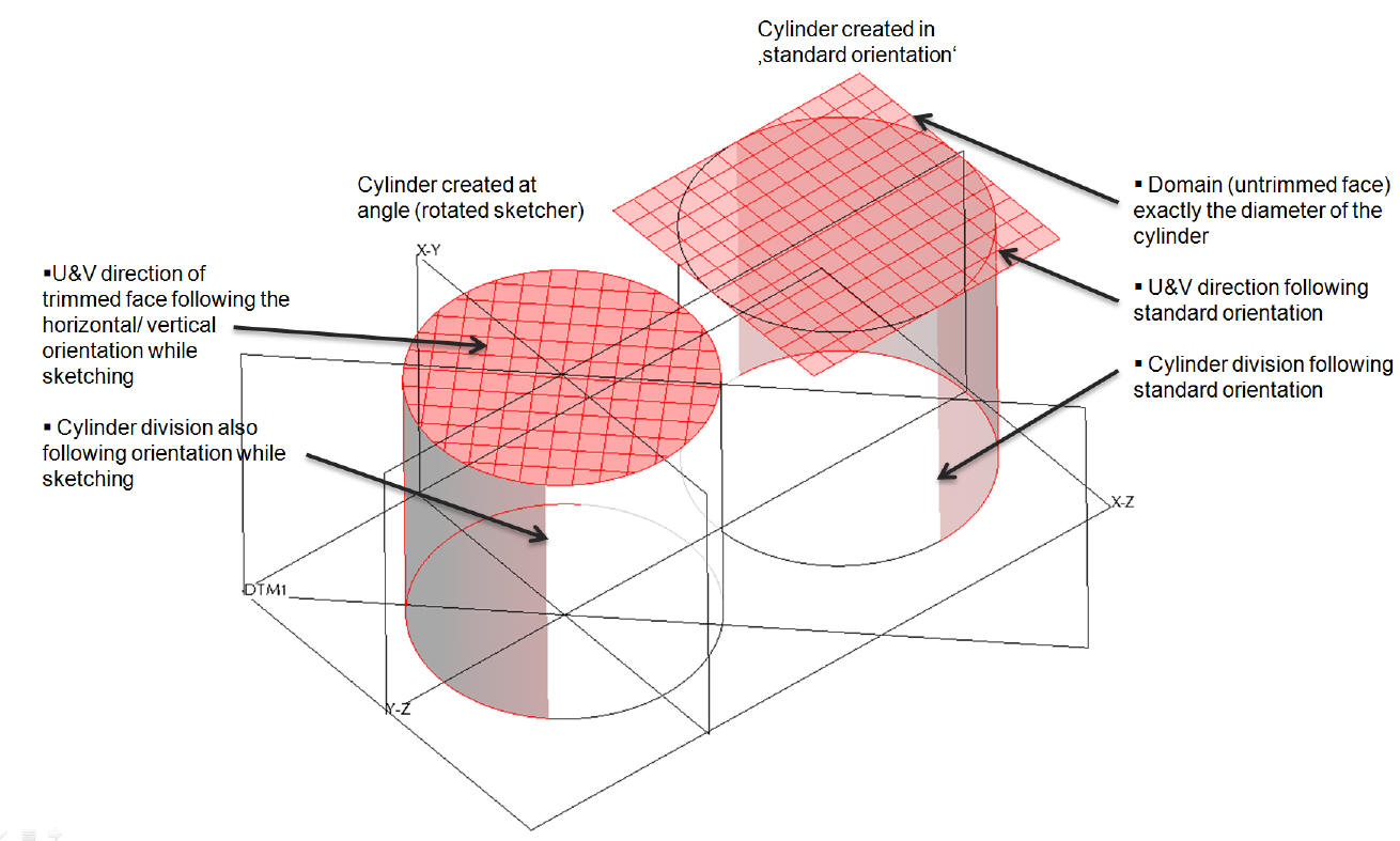
The endcaps of e.g. extruded cylinders (solid or surface) are NOT two semicircles. Those surfaces are trimmed faces based on a square domain surface (it can be seen when untrimming in IDD or creating a snapshot surface in 'independent geometry' (this was formerly in scantools) -> geometry -> surface -> from surface).
Nov 25, 2013
10:10 AM
- Mark as New
- Bookmark
- Subscribe
- Mute
- Subscribe to RSS Feed
- Permalink
- Notify Moderator
Please log in to access translation
Nov 25, 2013
10:10 AM
OK - the edges of the endcaps of the cylinders are two semicircles. Obviously there is a difference between a semicircle and the surface that is defined as bridging between two semicircles.
Without IDD I can't be certain, but what limits the size of the domain surface if not the extent of the semicircle edges or the extent of the model? Is it possible that the surface appears as it does because the software substitutes a rectangular patch display to work with instead of a plane with infinite extents?
In either case, two-semicircles are used for defining the end surface of the cylinder, and because of that there are two side surfaces on a cylinder.
Nov 26, 2013
03:36 AM
- Mark as New
- Bookmark
- Subscribe
- Mute
- Subscribe to RSS Feed
- Permalink
- Notify Moderator
Please log in to access translation
Nov 26, 2013
03:36 AM
I illustrated the above mentioned quickly:
Nov 26, 2013
10:47 AM
- Mark as New
- Bookmark
- Subscribe
- Mute
- Subscribe to RSS Feed
- Permalink
- Notify Moderator
Please log in to access translation
Nov 26, 2013
10:47 AM
I'm not surprised, but it hasn't any bearing on the data structure that is used.
Try the same with a closed spline loop instead of a circle.


