Turn on suggestions
Auto-suggest helps you quickly narrow down your search results by suggesting possible matches as you type.
Showing results for
Please log in to access translation
Turn on suggestions
Auto-suggest helps you quickly narrow down your search results by suggesting possible matches as you type.
Showing results for
Community Tip - If community subscription notifications are filling up your inbox you can set up a daily digest and get all your notifications in a single email. X
Translate the entire conversation x
Please log in to access translation
Options
- Subscribe to RSS Feed
- Mark Topic as New
- Mark Topic as Read
- Float this Topic for Current User
- Bookmark
- Subscribe
- Mute
- Printer Friendly Page
Outline of model
Jan 07, 2016
12:33 PM
- Mark as New
- Bookmark
- Subscribe
- Mute
- Subscribe to RSS Feed
- Permalink
- Notify Moderator
Please log in to access translation
Jan 07, 2016
12:33 PM
Outline of model
Good Morning,
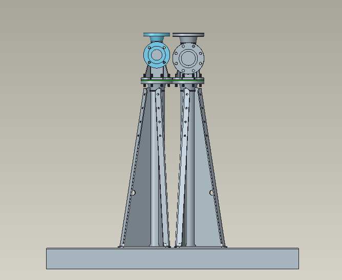
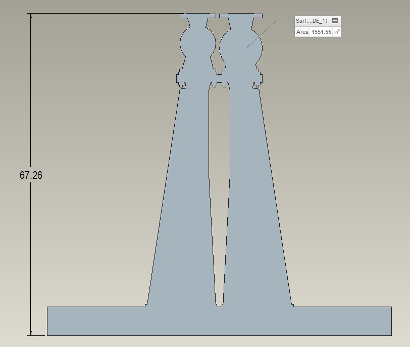
Does anyone know of an easy way to take the outline of a model to use as a sketch so I can calculate the area of an entire face of a model? I am trying to compute wind loads and I need the total area of a façade, not just a section? I am trying to go from the first picture to the second one in a much quicker fashion! Thank you.
Labels:
- Labels:
-
Creo Sketch
5 REPLIES 5
Jan 07, 2016
11:08 PM
- Mark as New
- Bookmark
- Subscribe
- Mute
- Subscribe to RSS Feed
- Permalink
- Notify Moderator
Please log in to access translation
Jan 07, 2016
11:08 PM
If you mean complete outline of the surface at given plane by "Outline of Model"
you can try using Intersect command, by selecting all the surfaces and an intersecting datum plane on which outline sketch will be generated,
Hope this helps.
Kudos,
-Prasad
Jan 07, 2016
11:23 PM
- Mark as New
- Bookmark
- Subscribe
- Mute
- Subscribe to RSS Feed
- Permalink
- Notify Moderator
Please log in to access translation
Jan 07, 2016
11:23 PM
Curve from cross section (datum tab: curve...)
You have options here. You can do this in part and assembly mode. Assembly mode will have multiple closed boundaries bordering each other.
If this is a single solid part already, you're golden.
If this is an assembly; to get that area calculation, you can do one of two things:
1) merge all the parts into a single part and section this "reference" part.
2) Curve from cross section and create a sketch (ultimately a fill feature to measure) by Projecting sections of the x-section curve to create your enclosed boundary.
I like method 1, where you create the reference part model because this should be easier to maintain a parametric relation through design iterations without too much fuss. The assembly section may well break each time an edge is added or deleted.
Jan 08, 2016
03:46 PM
- Mark as New
- Bookmark
- Subscribe
- Mute
- Subscribe to RSS Feed
- Permalink
- Notify Moderator
Please log in to access translation
Jan 08, 2016
03:46 PM
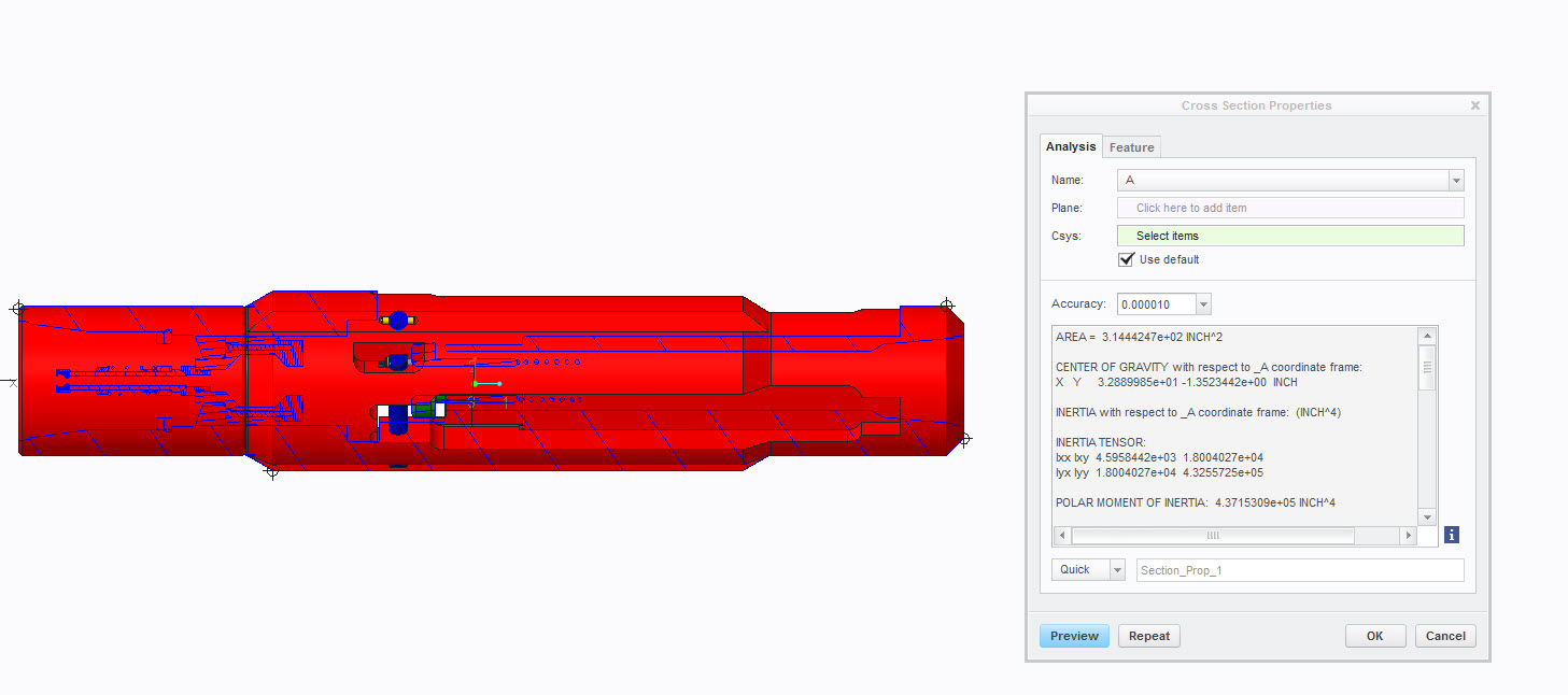
Edit: Sorry, I misread. Yes, Antonius's method 2 would work for filling in empty space. See comment below. You should be able to easily obtain the area of an assembly or part from the cross section properties. Analysis tab->mass properties dropdown->X-sec Mass Properties. Select the name of the cross section from the dropdown.
Jan 08, 2016
04:03 PM
- Mark as New
- Bookmark
- Subscribe
- Mute
- Subscribe to RSS Feed
- Permalink
- Notify Moderator
Please log in to access translation
Jan 08, 2016
04:03 PM
Antionius, wouldn't merging the parts still leave the empty areas needing to be filled? I would suggest simply using fill to define a closed sketch using projected edges and then measure the area.
Jan 08, 2016
06:27 PM
- Mark as New
- Bookmark
- Subscribe
- Mute
- Subscribe to RSS Feed
- Permalink
- Notify Moderator
Please log in to access translation
Jan 08, 2016
06:27 PM
Actually, Jeremy, your method is probably valid for assemblies if it sums the separate sectioned surfaces (I suspect it would).
I forgot about that analysis feature.
As for merge, the analysis of the x-section "should" create one or multiple closed loops. I just separated the sketch from the fill operation for clarity.
No matter what method, there are enough issues with the generic X-Section subroutines that any little niggle can cause this to fail.
It all depends on how critical it is to remain parametric over time; and how much pain your willing to bare each time you update the design.
Most times, the more basic the routing, the more reliable it will be.
If I needed to, I could make this work on a fairly reliable basis.