Community Tip - You can subscribe to a forum, label or individual post and receive email notifications when someone posts a new topic or reply. Learn more! X
- Community
- Creo+ and Creo Parametric
- Analysis
- Re: Calculating ASM projected area...
- Subscribe to RSS Feed
- Mark Topic as New
- Mark Topic as Read
- Float this Topic for Current User
- Bookmark
- Subscribe
- Mute
- Printer Friendly Page
Calculating ASM projected area...
- Mark as New
- Bookmark
- Subscribe
- Mute
- Subscribe to RSS Feed
- Permalink
- Notify Moderator
Calculating ASM projected area...
Does anyone know of an EASY way to get the projected area of an ASM in a particular direction normal to a plane?

I want to use this to find the maximum "windward frontal area" to use in performing Wind Loading calculations on a substation structure.
Thanks in advance of anyone's assistance! I appreciate the BoK(Bevy of Knowledge) of this community.![]()
![]()
- Labels:
-
General
- Mark as New
- Bookmark
- Subscribe
- Mute
- Subscribe to RSS Feed
- Permalink
- Notify Moderator
I replied before about creating a shrink wrap part representation. Does that not work?
- Mark as New
- Bookmark
- Subscribe
- Mute
- Subscribe to RSS Feed
- Permalink
- Notify Moderator
I tried that but to no avail… No “shrink wrapped part” did not work, but maybe I did something wrong! Got an example procedure you can share?
Any other ideas?… I would think I would be able to cast a “shadow” sketched outline of an ASM onto a datum plane of choice.
- Mark as New
- Bookmark
- Subscribe
- Mute
- Subscribe to RSS Feed
- Permalink
- Notify Moderator
You don't give enough information. Were you unable to create a shrinkwrap part? Are you not licensed to create one? What function did you try to generate the silhouette curve from the calculate the area from the shrinkwrap?
I don't really recall anyway to cast a silhouette in the base Creo modules, but you previously stated that it worked for parts and a shrinkwrap is a part. AFAIK silhouette curves are generated in the Mold module.
Here's shrinkwrap information per Creo 4; the same is basically true for earlier releases. Creo Parametric Help Center About Shrinkwrap Models
Anyway - are you looking to get the area of just some components of the assembly and not the entire assembly? You can create a simplified rep that has just those components and calculate the area of them alone. See Creo Parametric Help Center To Create a Simplified Representation from Selected Components
(Thanks to Jive! for promoting the links to their titles and to PTC Help! for not setting the titles to match the topics. Good job all around.)
- Mark as New
- Bookmark
- Subscribe
- Mute
- Subscribe to RSS Feed
- Permalink
- Notify Moderator
Ron,
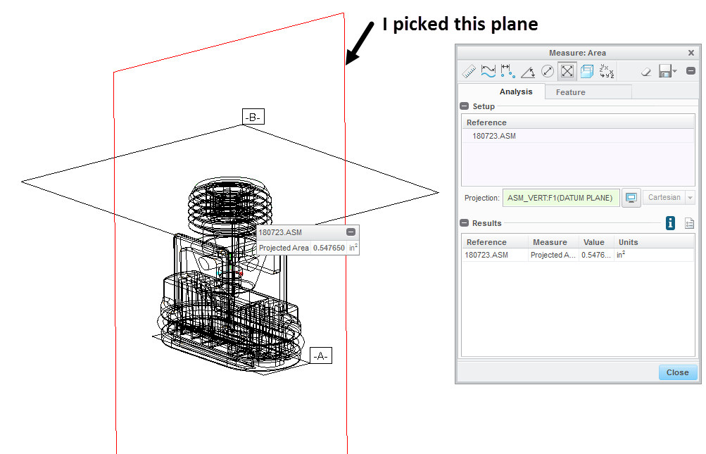
Am I correct to assume you used the Analysis, Measure, Area, Projected Area option? I'm getting a value by using that option:
1) Open up the Analysis, Measure: Area dialog box
2) For your reference go to the top of the model tree and select the ASM file (or if it's a sub-assembly in a larger assembly pick that file)
3) an Error will appear until you select a plane for the Projection direction. Once I did that the Projected Area measurement value showed up in the Results area
Be careful not to pick the icon next to your Projection direction selection - that changes your selection to the View Plane (can be deselected to return to your specified plane). Here's a picture of how it looked for me

- Mark as New
- Bookmark
- Subscribe
- Mute
- Subscribe to RSS Feed
- Permalink
- Notify Moderator
Mike, I am using CREO v2 M110 and tried your EXACT suggestion above before I created this discussion thread. However, it did not work as I expected it to! I thought that method would be the most logical one to follow, but after continuing to get the ERROR ICON in the value field I gave up. I guess I'll try this method again, following your exact procedure above, or will have to wait until CREO v3 gets installed on my PC later this year.
Thanks for the prompt response(s)!
- Mark as New
- Bookmark
- Subscribe
- Mute
- Subscribe to RSS Feed
- Permalink
- Notify Moderator
Hello @Ron(RonaldD.)Wh,
were you able to identify a solution that always works?
- Mark as New
- Bookmark
- Subscribe
- Mute
- Subscribe to RSS Feed
- Permalink
- Notify Moderator
Selecting the reference (PRT, sub-ASM component, or Top Level ASM) from within the Model Tree
and then, Selecting the Projection reference direction, again within the Model Tree
[ If you don't select a projection reference, then you get total surface area]
Shown in the dialog window (in CREO v4) below:
[cid:image001.png@01D65437.0A2241C0]
- Mark as New
- Bookmark
- Subscribe
- Mute
- Subscribe to RSS Feed
- Permalink
- Notify Moderator
Left out that I'm using Creo 3.0, M100
- Mark as New
- Bookmark
- Subscribe
- Mute
- Subscribe to RSS Feed
- Permalink
- Notify Moderator
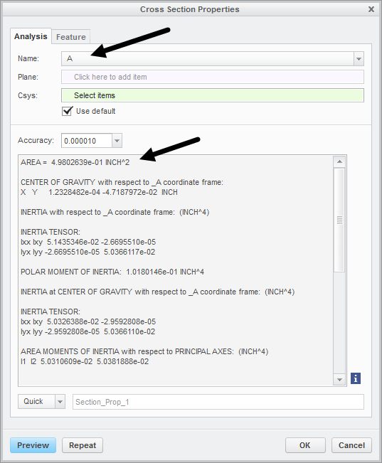
Another possibility - create a x-section using the plane you want to be normal to. Then go to Analysis, Mass Properties, X-Section Mass Properties. In the dialog box pick the name of your X-section and the results will include the Area of that X-Section (see below)


