Community Tip - You can Bookmark boards, posts or articles that you'd like to access again easily! X
- Community
- Creo+ and Creo Parametric
- Analysis
- Re: How to make a drive belt
- Subscribe to RSS Feed
- Mark Topic as New
- Mark Topic as Read
- Float this Topic for Current User
- Bookmark
- Subscribe
- Mute
- Printer Friendly Page
How to make a drive belt
- Mark as New
- Bookmark
- Subscribe
- Mute
- Subscribe to RSS Feed
- Permalink
- Notify Moderator
How to make a drive belt
Hello, so I want to make a drivebelt from these two parts:
I have tried making an assembly of the parts and then making a pattern and also doin this all in one part. I have tried (pattern function) both with points, but then the block wont follow the bend, and i have also tried with Curve pattern, But then it wont follow the bend good either, lower pic
I have done this with Flatten Quilt and flatten quilt deformation like this video:
Design belt with tool Flatten Quilt and Flatten Quilt Deformation in Creo 1.0 to Creo 3.0 - YouTube
But then it becomes a gap in the belt..
So how to do it good?
This thread is inactive and closed by the PTC Community Management Team. If you would like to provide a reply and re-open this thread, please notify the moderator and reference the thread. You may also use "Start a topic" button to ask a new question. Please be sure to include what version of the PTC product you are using so another community member knowledgeable about your version may be able to assist.
- Labels:
-
General
- Mark as New
- Bookmark
- Subscribe
- Mute
- Subscribe to RSS Feed
- Permalink
- Notify Moderator
You probably need to select the pattern origin. It is in options of the pattern creation.
What happens is that the object is transferred but it goes from the bounding box origin of the original object to an offset position which propagates the error as the pattern is distributed. Very annoying actually.
- Mark as New
- Bookmark
- Subscribe
- Mute
- Subscribe to RSS Feed
- Permalink
- Notify Moderator
- Mark as New
- Bookmark
- Subscribe
- Mute
- Subscribe to RSS Feed
- Permalink
- Notify Moderator
Hello how are you doin the pattern with the points?
I have done the point in the corner but I cant click anywhere when trying to make the dimension? (I cant select anything)?
- Mark as New
- Bookmark
- Subscribe
- Mute
- Subscribe to RSS Feed
- Permalink
- Notify Moderator
you can check up the file I attached in my previous reply. It explains everyth
- Mark as New
- Bookmark
- Subscribe
- Mute
- Subscribe to RSS Feed
- Permalink
- Notify Moderator
Hello i dont get how you made that last extrude.
1. So first you msut ahve done the extrude from the plane that the arrow points at.
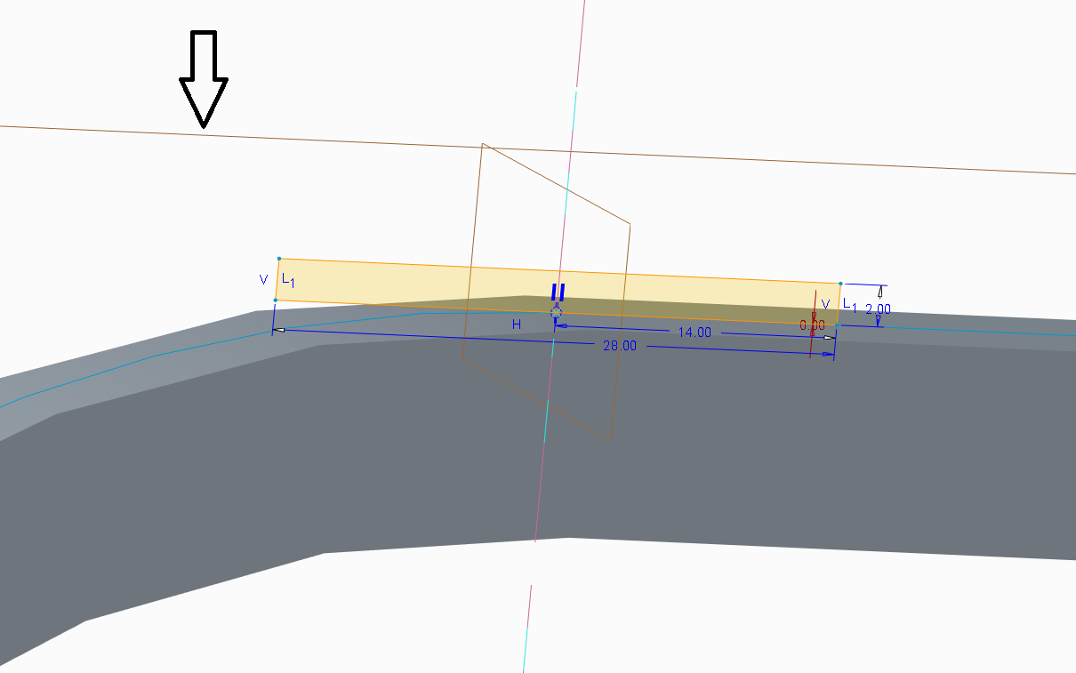
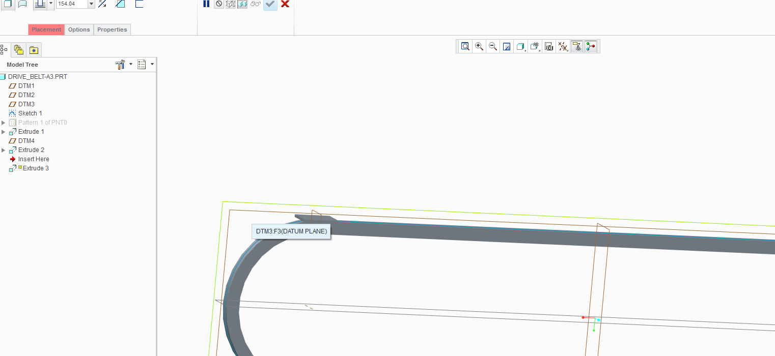
2. Then you made a reference on the plane that you set out that is in the group "cuts the extrude in half" and a reference on the first datum point that you had made a pattern of.
3. Then you made a contruction centerline that goes out from the reference of the datum point? and those two are coincident
And then you made an extrude from the datum point?
Any when I try to create the pattern when i have added this extrude it always fails to regenerate?
- Mark as New
- Bookmark
- Subscribe
- Mute
- Subscribe to RSS Feed
- Permalink
- Notify Moderator
Hi. There are 2 things you must follow when you create the tooth pattern on the belt:
1. datum point reference
- select the entire curve feature instead of its individual segment
2. section orientation
- use datum plane to control the orientation.
- each point has its own datum plane to do this job
- section must reference to both datum point and datum plane only. DO NOT use other references.
If you can attach your file, I will help to look at what you have done and correct it for you. Thanks
- Mark as New
- Bookmark
- Subscribe
- Mute
- Subscribe to RSS Feed
- Permalink
- Notify Moderator
Hello that would be very kind of you!
Here is the file!
- Mark as New
- Bookmark
- Subscribe
- Mute
- Subscribe to RSS Feed
- Permalink
- Notify Moderator
Unfortunatelly the file is created in Educational version and cannot be opened in Commercial version.
MH
Martin Hanák
- Mark as New
- Bookmark
- Subscribe
- Mute
- Subscribe to RSS Feed
- Permalink
- Notify Moderator
I will take pictures!
1. So first i choose extrude on the plane shown in first pic (DTM3)
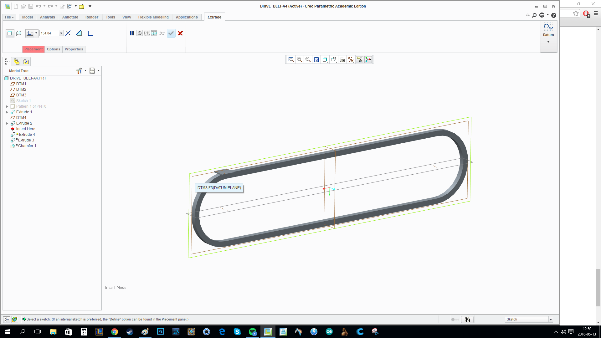
2. Then I pick my references, the datum plane ( pic 2) and the datum point (pic 3) ( pic 4 shows whole sketch)
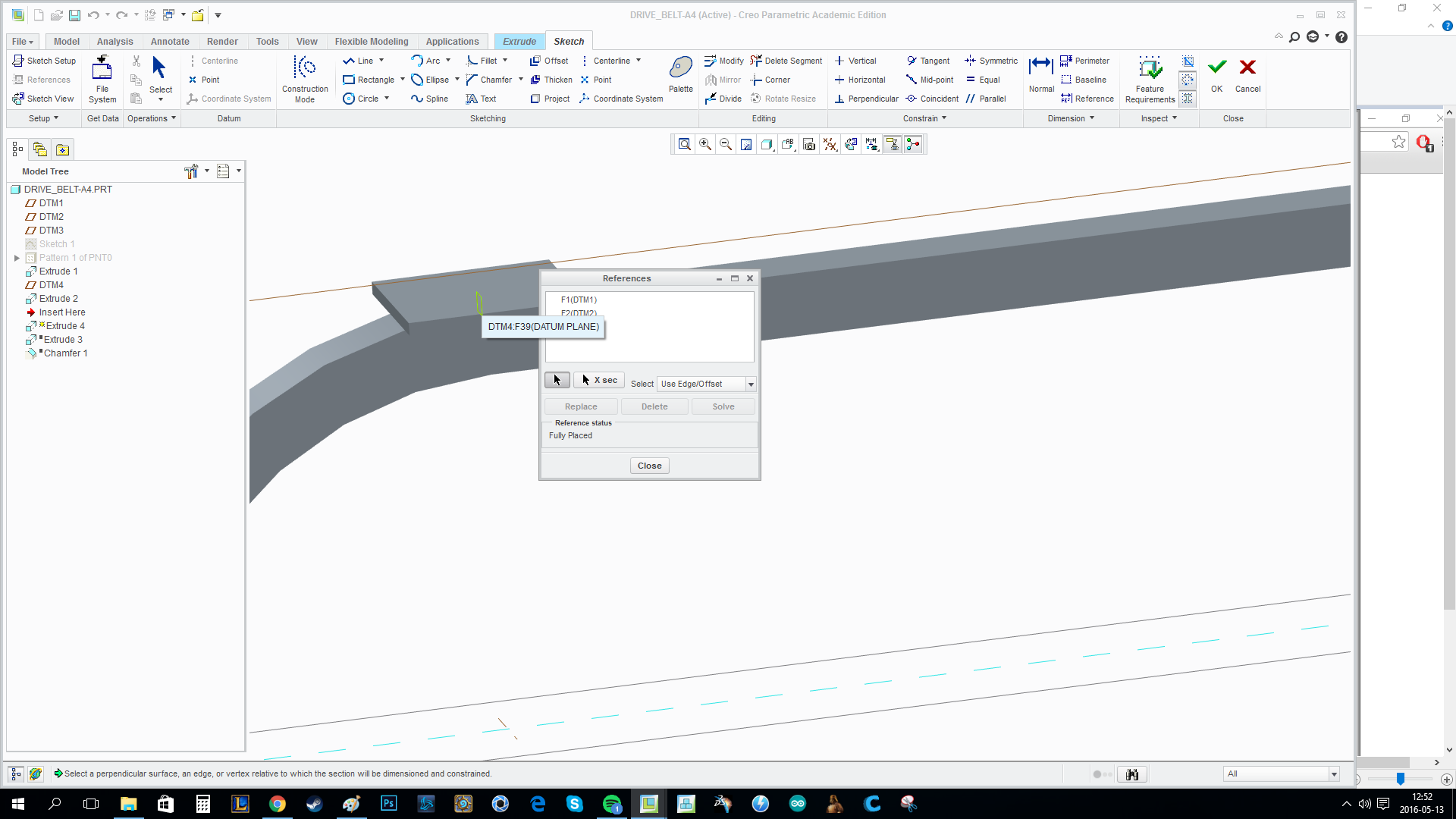
3. I put out my centerline on the datum point that I amde a reference in pic 3
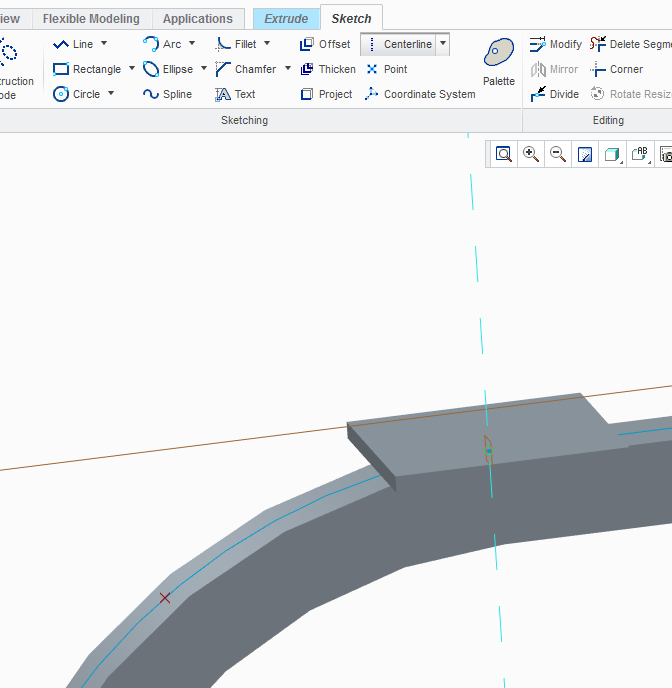
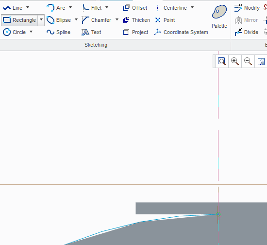
4. I use rectangle to get the shape of the extrude over the reference point and then set out the distances
5. Then i make my extrude
6. Then i group the two extrudes and datum plane
7. Then i make a pattern wehich fails
- Mark as New
- Bookmark
- Subscribe
- Mute
- Subscribe to RSS Feed
- Permalink
- Notify Moderator
as mentioned by Martin, I am unable to open the file.![]()
- Mark as New
- Bookmark
- Subscribe
- Mute
- Subscribe to RSS Feed
- Permalink
- Notify Moderator
I amde all my steps with with pics above ![]()
- Mark as New
- Bookmark
- Subscribe
- Mute
- Subscribe to RSS Feed
- Permalink
- Notify Moderator
Do this when creating you tooth feature:
1. Sketch Orientation
- sketching plane DTM3, but the orientation MUST be DTM4 (right or left)
2. Section references
- just use PNT0 and DTM4 as your section references, NOTHING else.
Try it and see if it works.
- Mark as New
- Bookmark
- Subscribe
- Mute
- Subscribe to RSS Feed
- Permalink
- Notify Moderator
Also,
1. when you create PNT0, use entire curve as reference
2. when you create DTM3, use PNT0 (through) and entire curve (normal)
3. group PNT0, DTM3 and EXTRUDE in a group
4. pattern the group
- Mark as New
- Bookmark
- Subscribe
- Mute
- Subscribe to RSS Feed
- Permalink
- Notify Moderator
Now I have used your previously file, I so the points are the same as u did, I have just changed the dimensions.
what do you mean by " sketching plane DTM3, but the orientation MUST be DTM4 (right or left)"
- Mark as New
- Bookmark
- Subscribe
- Mute
- Subscribe to RSS Feed
- Permalink
- Notify Moderator
when you set the orientation of yr sketch, you MUST use DTM4 as the reference (either as right, left , top or bottom plane depending on how you would like to orientate you section)
- Mark as New
- Bookmark
- Subscribe
- Mute
- Subscribe to RSS Feed
- Permalink
- Notify Moderator
When you define the point, right click so that you select the entire outer sketch and then set your offset (probably 0 for this). When you pattern, the points should follow the sketch profile.


