
Turn on suggestions
Auto-suggest helps you quickly narrow down your search results by suggesting possible matches as you type.
Showing results for
Please log in to access translation
Turn on suggestions
Auto-suggest helps you quickly narrow down your search results by suggesting possible matches as you type.
Showing results for
Community Tip - Did you get an answer that solved your problem? Please mark it as an Accepted Solution so others with the same problem can find the answer easily. X
- Community
- Creo+ and Creo Parametric
- Analysis
- Interference / overlapping geometry handling
Translate the entire conversation x
Please log in to access translation
Options
- Subscribe to RSS Feed
- Mark Topic as New
- Mark Topic as Read
- Float this Topic for Current User
- Bookmark
- Subscribe
- Mute
- Printer Friendly Page
Interference / overlapping geometry handling
Jan 07, 2019
09:07 AM
- Mark as New
- Bookmark
- Subscribe
- Mute
- Subscribe to RSS Feed
- Permalink
- Notify Moderator
Please log in to access translation
Jan 07, 2019
09:07 AM
Interference / overlapping geometry handling
Hi everyone,
I've played a bit more with it and i found out someting a bit tricky :
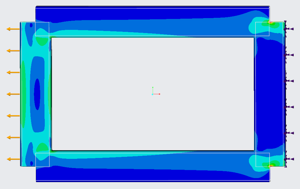
If you let some interferences in the model, such as in the attached screenshot, you won't get any warning or failure, the calculation runs smoothly.
But it looks like the system is assuming that you put twice the material in the overlapping areas. I've done the same model with adjusted profiles and the result is way different.
So maybe, we should at least shoot a popup message to help identify the overlapping regions and ask for validation that those areas will be treated with the combinaison of the overlapping geometries before calculation.
Solved! Go to Solution.
ACCEPTED SOLUTION
Accepted Solutions
Jan 16, 2019
01:27 PM
- Mark as New
- Bookmark
- Subscribe
- Mute
- Subscribe to RSS Feed
- Permalink
- Notify Moderator
Please log in to access translation
Jan 16, 2019
01:27 PM
Hi Michel,
I've gotten a little more information to share. The overall assumption is that the interference is small or should be small, so the simplest/fastest solving approach is used. The interference doesn't try to do any blending of materials, it takes the material properties from the part model that is highest in the model tree currently and uses that for the interference zone.
I hope that helps answer your question.
Regards,
Todd Kraft
5 REPLIES 5
Jan 09, 2019
11:24 AM
- Mark as New
- Bookmark
- Subscribe
- Mute
- Subscribe to RSS Feed
- Permalink
- Notify Moderator
Please log in to access translation
Jan 09, 2019
11:24 AM
SoretteMichel,
Thank you for the feedback. I don't recall discussions so far about how interference in the assemblies are handled....so this is an interesting topic to explore.
In a few models that I have tried with interference and without interference....I don't see a behavior that looks like 'twice' the material is there. I get the same results with and without interference. I've also validated this in Ansys Discovery Live.
So possibly the difference in the models has to do with the performance of the graphics card fidelity used to solve in those corners of the models. Did you look at the 'deformation'? Does the deformation result look like twice the material is there? The sharp corners that you indicate will be troublesome for FEA programs in general due to stress concentrations or singularities in those areas.
I would like to investigate further if the deformation results show a significant difference between interference and no interference. Can you please let me know the differences for that measure?
Thank you for your time,
Todd Kraft
PTC CAD Product Manager
Jan 09, 2019
12:03 PM
- Mark as New
- Bookmark
- Subscribe
- Mute
- Subscribe to RSS Feed
- Permalink
- Notify Moderator
Please log in to access translation
Jan 09, 2019
12:03 PM
Hello Todd,
I've done the tests and added a third comparison model (merged components into a single one)
please find the screenshots attached. We can still see the influence of the double material in both stress and displacements in the overlapping geometry area compared to the merged or adjusted models (stress or displacements franges frontiers are deformed while approeaching the overlapping area).
I'm available for a webex if you need more info on this topic,
Hope this helps,
Jan 11, 2019
08:25 AM
- Mark as New
- Bookmark
- Subscribe
- Mute
- Subscribe to RSS Feed
- Permalink
- Notify Moderator
Please log in to access translation
Jan 11, 2019
08:25 AM
Hi again,
I've performed some more tests with a 100% interference component : main component is a plate with a hole and the second one is a small cylinder completely interfering the plate close to the hole (in the high stress area).
What i've found out is really strange : if both components have the same material, the system seems to do as if the cylinder was not existing (nothing can be seen on the area compared to the symmetrical area). But if i put different materials, then the comportment is really different and we can clearly see the stress concentration around the cylinder border.
I'm really curious to know exactly how the system is handling those cases so we can anticipate it in the model preparation.
Jan 11, 2019
01:15 PM
- Mark as New
- Bookmark
- Subscribe
- Mute
- Subscribe to RSS Feed
- Permalink
- Notify Moderator
Please log in to access translation
Jan 11, 2019
01:15 PM
Hi Michel,
I will look further into finding out what should happen when two part geometries occupy the same space and they have different material properties.
Thank you,
Todd Kraft
Jan 16, 2019
01:27 PM
- Mark as New
- Bookmark
- Subscribe
- Mute
- Subscribe to RSS Feed
- Permalink
- Notify Moderator
Please log in to access translation
Jan 16, 2019
01:27 PM
Hi Michel,
I've gotten a little more information to share. The overall assumption is that the interference is small or should be small, so the simplest/fastest solving approach is used. The interference doesn't try to do any blending of materials, it takes the material properties from the part model that is highest in the model tree currently and uses that for the interference zone.
I hope that helps answer your question.
Regards,
Todd Kraft
Announcements


Top Tags
