
Turn on suggestions
Auto-suggest helps you quickly narrow down your search results by suggesting possible matches as you type.
Showing results for
Please log in to access translation
Turn on suggestions
Auto-suggest helps you quickly narrow down your search results by suggesting possible matches as you type.
Showing results for
Community Tip - Need to share some code when posting a question or reply? Make sure to use the "Insert code sample" menu option. Learn more! X
- Community
- Creo+ and Creo Parametric
- Analysis
- Issues Adding Ambient Airflow to Vacuum Simulation...
Translate the entire conversation x
Please log in to access translation
Options
- Subscribe to RSS Feed
- Mark Topic as New
- Mark Topic as Read
- Float this Topic for Current User
- Bookmark
- Subscribe
- Mute
- Printer Friendly Page
Issues Adding Ambient Airflow to Vacuum Simulation in Creo Flow
Apr 02, 2025
09:09 AM
- Mark as New
- Bookmark
- Subscribe
- Mute
- Subscribe to RSS Feed
- Permalink
- Notify Moderator
Please log in to access translation
Apr 02, 2025
09:09 AM
Issues Adding Ambient Airflow to Vacuum Simulation in Creo Flow
Hello everyone,
I am currently working on a Creo Flow Analysis for a vacuum system. I was able to successfully set up an internal flow simulation, but I am facing errors when trying to include the ambient airflow around the nozzle.
What I have set up successfully:
Internal flow only:
Inlet (nozzle entry): Set as 101325 Pa (atmospheric pressure).
Outlet (nozzle exit, connected to the vacuum system): Defined as Volumetric Flux 400 m³/h (0.111 m³/s).
This setup runs without issues.
What I am trying to add:
I want to simulate how air is being drawn from the surroundings into the nozzle.
To do this, I added a large surrounding box to represent the air environment.
The walls of the box are defined as inlet and outlet pressures (atmospheric pressure, 101325 Pa).
The issue:
When I include the ambient air domain, I get errors on the inlet and outlet boundaries of the nozzle.
It seems like Creo does not handle both the internal flow and external airflow together properly.
My goal is to see where the nozzle pulls air from and how strong the airflow is in different directions.
Has anyone successfully set up a vacuum suction simulation with an external air domain in Creo Flow Analysis? Any advice on the correct boundary conditions or setup would be greatly appreciated! I've also added images for clarification.
Best regards,
Siebe
Labels:
- Labels:
-
Comput_Fluid Dynamic
8 REPLIES 8
Apr 02, 2025
10:02 AM
- Mark as New
- Bookmark
- Subscribe
- Mute
- Subscribe to RSS Feed
- Permalink
- Notify Moderator
Please log in to access translation
Apr 02, 2025
10:02 AM
I looks like your inlet and outlet are within the external domain. I wonder if that has something to do with your problem. Try creating another fluid domain that mates with your inlet but doesn't encompase either the inlet or the outlet. You will end up with an interface where you now have the inlet. The walls of the new domain would be pressure inlets.
Apr 09, 2025
07:15 AM
- Mark as New
- Bookmark
- Subscribe
- Mute
- Subscribe to RSS Feed
- Permalink
- Notify Moderator
Please log in to access translation
Apr 09, 2025
07:15 AM
Hi again,
Thanks once more for your earlier suggestion!
Since my last message, I’ve updated the model to include a second internal nozzle. Here's the current setup:
On the left, a gas nozzle connected to an argon cylinder (internal domain 1);
On the right, a suction nozzle connected to a vacuum source (pulling 400 m³/h, internal domain 2);
A small interface domain was added between the nozzles and the surrounding air, as you suggested.
Unfortunately, I'm still running into issues:
I continue to get boundary condition errors at both internal domains inlet and outlet;
The simulation appears to ignore the internal domains entirely—it only processes flow within the interface and the external box;
The physical behavior I aim to simulate is not being captured: the suction nozzle should draw in both the argon from the gas nozzle and ambient air from the surroundings (e.g., also from above or the sides), but the current setup does not allow for this (only in front of the inlet).
My goal is to:
Accurately simulate the airflow path from the gas inlet to the suction outlet;
Visualize how well the suction system performs;
Understand where the incoming air is coming from (directionally);
And include entrainment of ambient air, not just a direct connection between the two nozzles.
Do you have any insight into how I can correctly define the interfaces and boundary conditions to make sure internal and external domains communicate properly? Or what would be the correct way to model this type of mixed suction and ambient inflow scenario?
Any guidance would be greatly appreciated!
Best regards,
Siebe
Apr 09, 2025
08:49 AM
- Mark as New
- Bookmark
- Subscribe
- Mute
- Subscribe to RSS Feed
- Permalink
- Notify Moderator
Please log in to access translation
Apr 09, 2025
08:49 AM
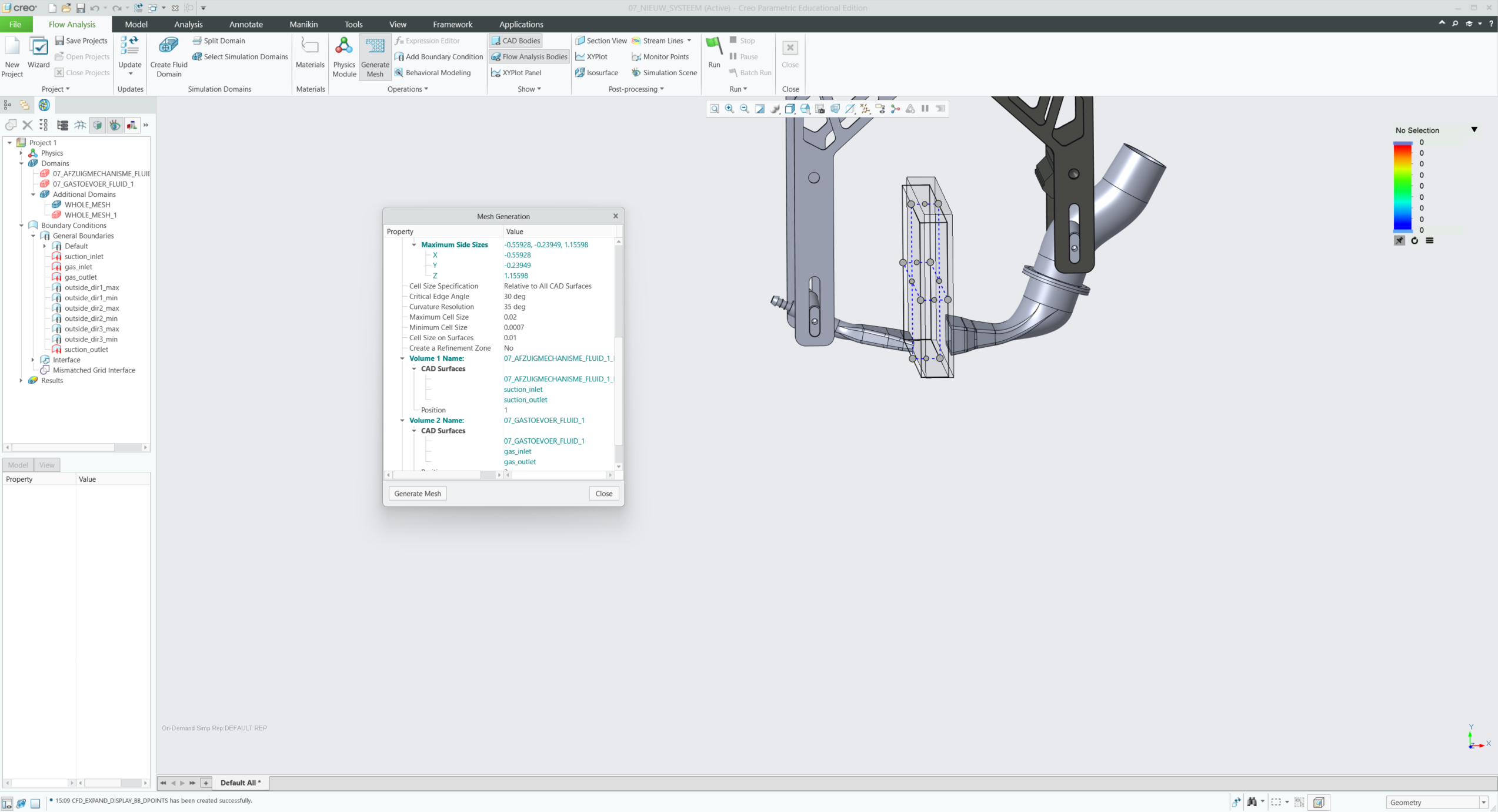
I see that the first two domains and some of your boundary conditions are highlighted in red. This makes me wonder if your mesh is good and if your boundary conditions lost their reference surfaces. What are your settings for mesh size?
Apr 09, 2025
09:18 AM
- Mark as New
- Bookmark
- Subscribe
- Mute
- Subscribe to RSS Feed
- Permalink
- Notify Moderator
Please log in to access translation
Apr 09, 2025
09:18 AM
Hi,
Thanks for your response! I’ve added several screenshots as attachments that show the current setup, including the mesh, geometry, and boundary condition definitions. I hope this gives a clearer picture of the situation.
One thing I noticed: when I generate the mesh, both internal flow bodies (from the gas and suction nozzles) seem to disappear, and only the external domain remains meshed. This is also visible in one of the attached images.
Let me know if you need anything else!
Best regards,
Siebe
Apr 09, 2025
11:01 AM
- Mark as New
- Bookmark
- Subscribe
- Mute
- Subscribe to RSS Feed
- Permalink
- Notify Moderator
Please log in to access translation
Apr 09, 2025
11:01 AM
There is no material assignment on *_Body_1.

Do you have a mixture of air and argon? That would require a certain physics model. You'll probably need Multicomponent Mixing, which allows mixing of multiple gases and densities. I don't have any experience with that other than doing tutorials.
Apr 10, 2025
12:33 PM
- Mark as New
- Bookmark
- Subscribe
- Mute
- Subscribe to RSS Feed
- Permalink
- Notify Moderator
Please log in to access translation
Apr 10, 2025
12:33 PM
Yes, exactly — in the suction nozzle, both ambient air and the added argon gas are being drawn in and mixed, so it's definitely a multicomponent flow case.
Do you happen to know of any good tutorials or documentation on how to set this up in Creo Flow Analysis? Or maybe someone in this group/community who has done something similar before and could point me in the right direction?
Thanks a lot for the help already!
Apr 10, 2025
04:06 PM
- Mark as New
- Bookmark
- Subscribe
- Mute
- Subscribe to RSS Feed
- Permalink
- Notify Moderator
Please log in to access translation
Apr 10, 2025
04:06 PM
I find it a little difficult to find good CFD training on the PTC site. There is a list of CFD webcasts in this community that might help you.

And there is this...
Jun 10, 2025
03:26 PM
- Mark as New
- Bookmark
- Subscribe
- Mute
- Subscribe to RSS Feed
- Permalink
- Notify Moderator
Please log in to access translation
Jun 10, 2025
03:26 PM
Hi you could get technique support from Simerics for any CFA questions. Please contact your ptc support so we can step in and help your cases. thanks.
Announcements


Top Tags
