Community Tip - Your Friends List is a way to easily have access to the community members that you interact with the most! X
- Subscribe to RSS Feed
- Mark Topic as New
- Mark Topic as Read
- Float this Topic for Current User
- Bookmark
- Subscribe
- Mute
- Printer Friendly Page
Auxiliary views in CadProcess, revisited
- Mark as New
- Bookmark
- Subscribe
- Mute
- Subscribe to RSS Feed
- Permalink
- Notify Moderator
Auxiliary views in CadProcess, revisited
So I asked this question a few years ago without much success, but it's so frustrating on a daily basis that I need to bring it up again. Since I don't have a choice, I have learned to get along without the ability to rotate the viewing angle, or to create and save new views, but it's like getting used to driving a car with no reverse - yeah, you can do it if you have to, but it takes lots of extra time and planning, and it sure would make life a whole lot easier if I could just back up when I needed to.
What I still don't understand is why the 4 standard isometric views are not included as options to rotate to - and - since they aren't availble, why there is no way to create and save new views. All I want is to be able to rotate the VIEW (or camera angle, or viewing perspective, or whatever you want to call it) in 90 degree increments around the model by simply clicking on a corresponding view button WITHOUT having to select everything and rotate the actual model (in exactly the same way that you can instantly change from an isometric top view (looking down at the model) to an isometric bottom view (looking up at it from underneath) by clicking on the corresponding button).
I'm also baffled as to why no one sees this as a major discrepancy, when every other 3d software out there has some kind of provision for this essential function. Any thoughts?
- Tags:
- cadprocess
- rotate
- view
- Mark as New
- Bookmark
- Subscribe
- Mute
- Subscribe to RSS Feed
- Permalink
- Notify Moderator
Hello!
Which version of Arbortext IsoDraw are you using? A little later I'll describe how I do in this situation (for the required orientation of a model).
- Mark as New
- Bookmark
- Subscribe
- Mute
- Subscribe to RSS Feed
- Permalink
- Notify Moderator
I normally use 7.0 because it's slightly less buggy and irritating than 7.1, but we have everything between 6.0 and 7.2, since we have to deliver to various customers who still use all of those versions. At this point, I would gladly switch to any version that would allow for an option to save new views in CADprocess.
- Mark as New
- Bookmark
- Subscribe
- Mute
- Subscribe to RSS Feed
- Permalink
- Notify Moderator
That's how I do in this case. First you need to add its toolbar "3D Tools", adding there new views: "View X", "View Y", "View Z", also, "Isometric" and "Dimetric". In the main navigation menu "Window" -> "Toolbars ...", etc., choose toolbar "3D Tools" and select "Edit" - adding the above described views. In order to rotate the model with the desired angle of rotation, must use the "Rotation" with key "Shift", which allows you to enter an exact value for angle.
- Mark as New
- Bookmark
- Subscribe
- Mute
- Subscribe to RSS Feed
- Permalink
- Notify Moderator
Yes, that's exactly what I have been doing for years, and am trying to avoid. The existing preset view options (X, Y, Z, Isometric, Dimetric, etc) work very well, but the whole point for posting this question is that I do not want to physically rotate the model just to view it from a different angle (than what is available with these limited preset options).
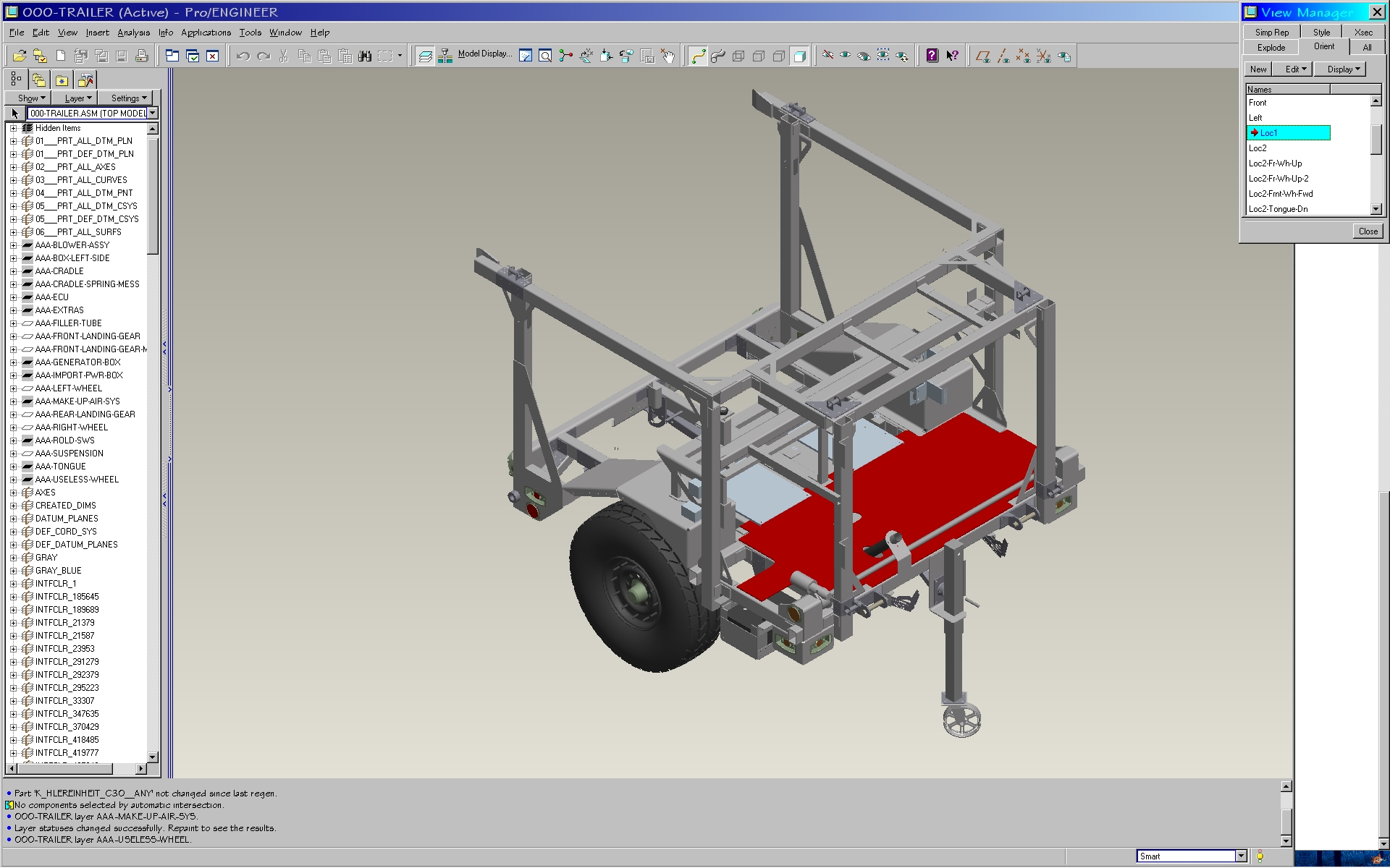
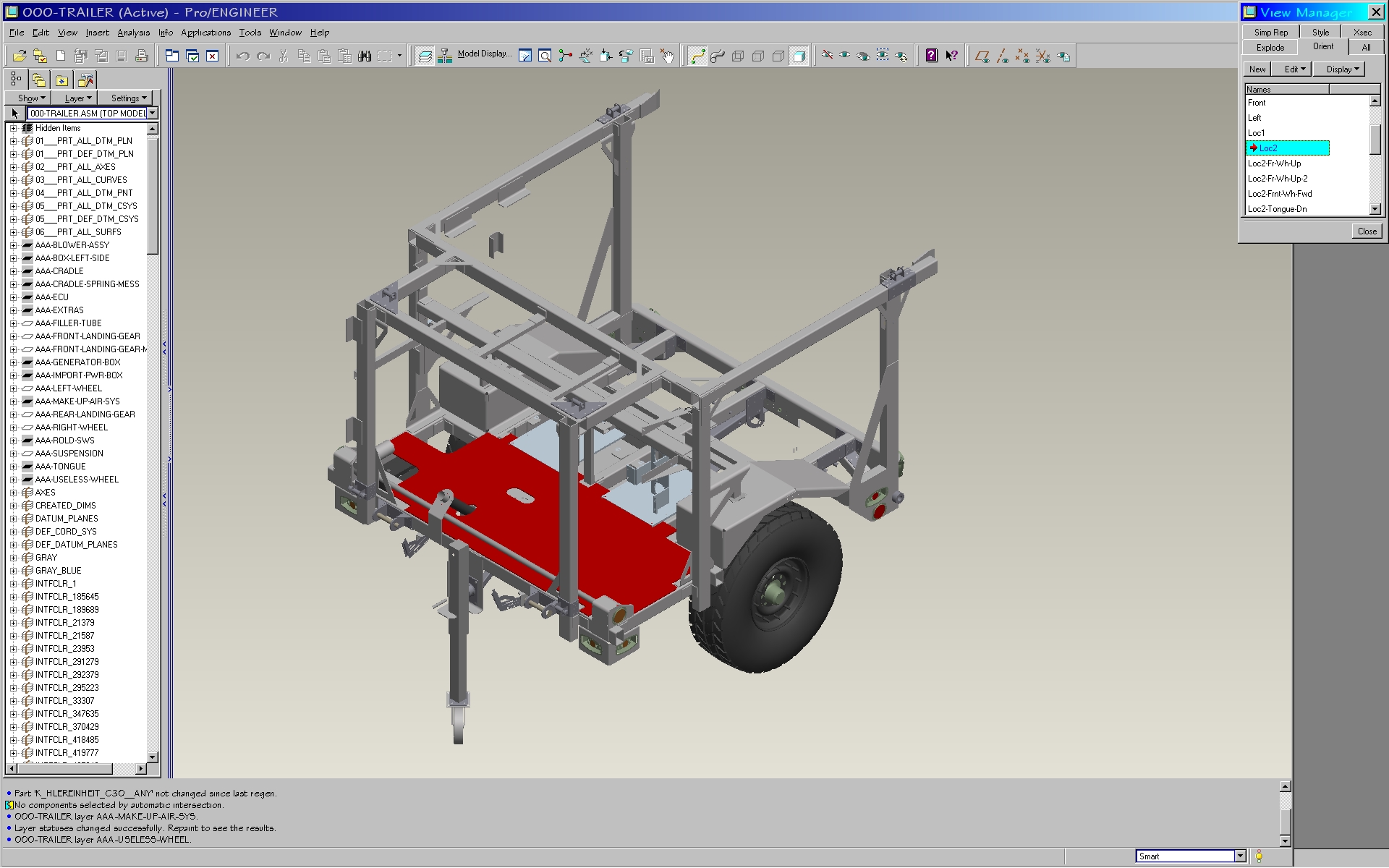
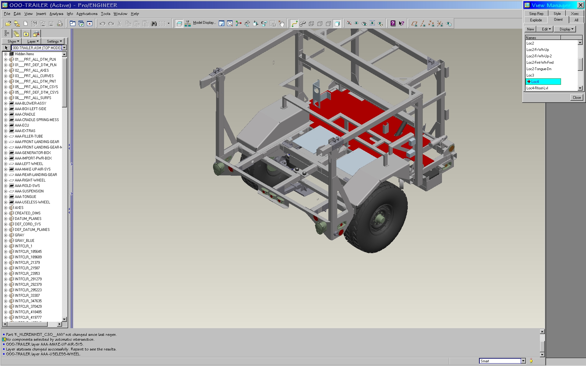
I have attached some screen shots to show what I'm talking about (in Pro-E). The model shown is not rotating, and nothing is selected, I am simply choosing different VIEWS that I had previously saved, which spin around the model in 90 degree increments. These 4 views are essential to creating illustrations. Physically selecting and rotating HUGE models, which sometimes have parts distributed on up to 50 different layers, is an enormously inefficient and error prone way of doing business.


- Mark as New
- Bookmark
- Subscribe
- Mute
- Subscribe to RSS Feed
- Permalink
- Notify Moderator
I think there will be useful to create macros for each of the required views (ie, select the entire 3D model, then is rotated it an axis necessary for us on a certain angle), such as "Loc1.ism", "Loc2.ism", "Loc3.ism", "Loc4.ism".
- Mark as New
- Bookmark
- Subscribe
- Mute
- Subscribe to RSS Feed
- Permalink
- Notify Moderator
I suppose that would be better than nothing - if anyone has written such a macro, let me know
- Although I still think it's ridiculous to have to rotate the model. It's like this: if you are standing on one side of a large object (like a truck or an airplane or something), and you want to see the other side, which makes more sense: a) lift the entire vehicle and rotate it, or b) walk around to the other side?
- Mark as New
- Bookmark
- Subscribe
- Mute
- Subscribe to RSS Feed
- Permalink
- Notify Moderator
Chris,
I have created a simple macro which rotates the 3D assembly on 90 degree. The macro file "View_90.ism" needs to be placed in a following folder: "C:\Documents and Settings\UserName\Application Data\PTC\IsoDraw\Macros" (I use on Win Vista 32-bit the following way: "C:\Users\user\AppData\Roaming\PTC\IsoDraw\Macros"). Also the given macro can be added as the button on the panel 3D Tools and to use it as a command - see attach.
- Mark as New
- Bookmark
- Subscribe
- Mute
- Subscribe to RSS Feed
- Permalink
- Notify Moderator
Until PTC realizes that they need to add the missing isometric view options, this is a very helpful work-around. Thank you Vladimir.
Since this macro is still rotating the actual model (instead of just changing the view), I renamed it as 'Rotate_90', and added another option called 'Rotate_180' (see attached).


