
Turn on suggestions
Auto-suggest helps you quickly narrow down your search results by suggesting possible matches as you type.
Showing results for
Please log in to access translation
Turn on suggestions
Auto-suggest helps you quickly narrow down your search results by suggesting possible matches as you type.
Showing results for
Community Tip - If community subscription notifications are filling up your inbox you can set up a daily digest and get all your notifications in a single email. X
- Community
- Creo (Previous to May 2018)
- Creo Modeling Questions
- Re: 3D curve using 2D arc segments
Translate the entire conversation x
Please log in to access translation
Options
- Subscribe to RSS Feed
- Mark Topic as New
- Mark Topic as Read
- Float this Topic for Current User
- Bookmark
- Subscribe
- Mute
- Printer Friendly Page
3D curve using 2D arc segments
Jul 09, 2015
03:21 AM
- Mark as New
- Bookmark
- Subscribe
- Mute
- Subscribe to RSS Feed
- Permalink
- Notify Moderator
Please log in to access translation
Jul 09, 2015
03:21 AM
3D curve using 2D arc segments
I am looking for a solution to create a 3D loop similar to one shown in the attached picture out of 2D arc segments.The 2D arc can have straight portion in the ends. Idea is to fabricate a 3D pipe using 2D bent pipes. Any suggestions to address this?
4 REPLIES 4
Jul 09, 2015
06:21 PM
- Mark as New
- Bookmark
- Subscribe
- Mute
- Subscribe to RSS Feed
- Permalink
- Notify Moderator
Please log in to access translation
Jul 09, 2015
06:21 PM
Try this:
Select first curve > Again select the same curve (highlight in bold) > Copy (CTRL + C) > +SHIFT > Select other curves and finish. This will give you a complete curve which can use for further operations.
Jul 10, 2015
01:13 AM
- Mark as New
- Bookmark
- Subscribe
- Mute
- Subscribe to RSS Feed
- Permalink
- Notify Moderator
Please log in to access translation
Jul 10, 2015
01:13 AM
Sorry if I am not very clear with my requirement. I donot want to copy the cuver form proe. I want to create a new 3D loop in proe which will be the centre line of the a pipe weldment. During this I will have only 2D bent pipe sections (similar to arc in 2d) which need to be assembled at the end of each section and orient in right direction to form the 3D curve. I will be having top end and bottom end of the 3D curve given as fixed one. Now in need to find out how to arrive on the individual pipe segments to form a circular loop and reach the top point from bottom point. Hope I am bit more clear now, please refer another loop attached which will give more clarity.
Jul 10, 2015
01:58 PM
- Mark as New
- Bookmark
- Subscribe
- Mute
- Subscribe to RSS Feed
- Permalink
- Notify Moderator
Please log in to access translation
Jul 10, 2015
01:58 PM
Hi, welcome to the community.
If I understand correctly, you're trying to make a tube weldment which follows a complex 3D trajectory, but is made out simpler segments (2D trajectories, or tubes bent in only a single plane).
Start by making your 3D trajectory. One way would be to create a composite 3D curve by intersecting two 2D sketches. Create two 2D sketches on planes perpendicular to each other then intersect them with the "Intersect" command. This gives you a composite 3D curve which follows the profiles in both base sketches.
I can think of two ways you can take the 3D curve and cut it up into several segments. One way would be to place several datum points on the curve where you want the pipe segments to start/end. Then use the trim command to trim the curve at those datum points. You'll have to flip the trim arrows a couple times to tell it to keep both sides of the trimmed curve. Repeat this for any other pipe segments.
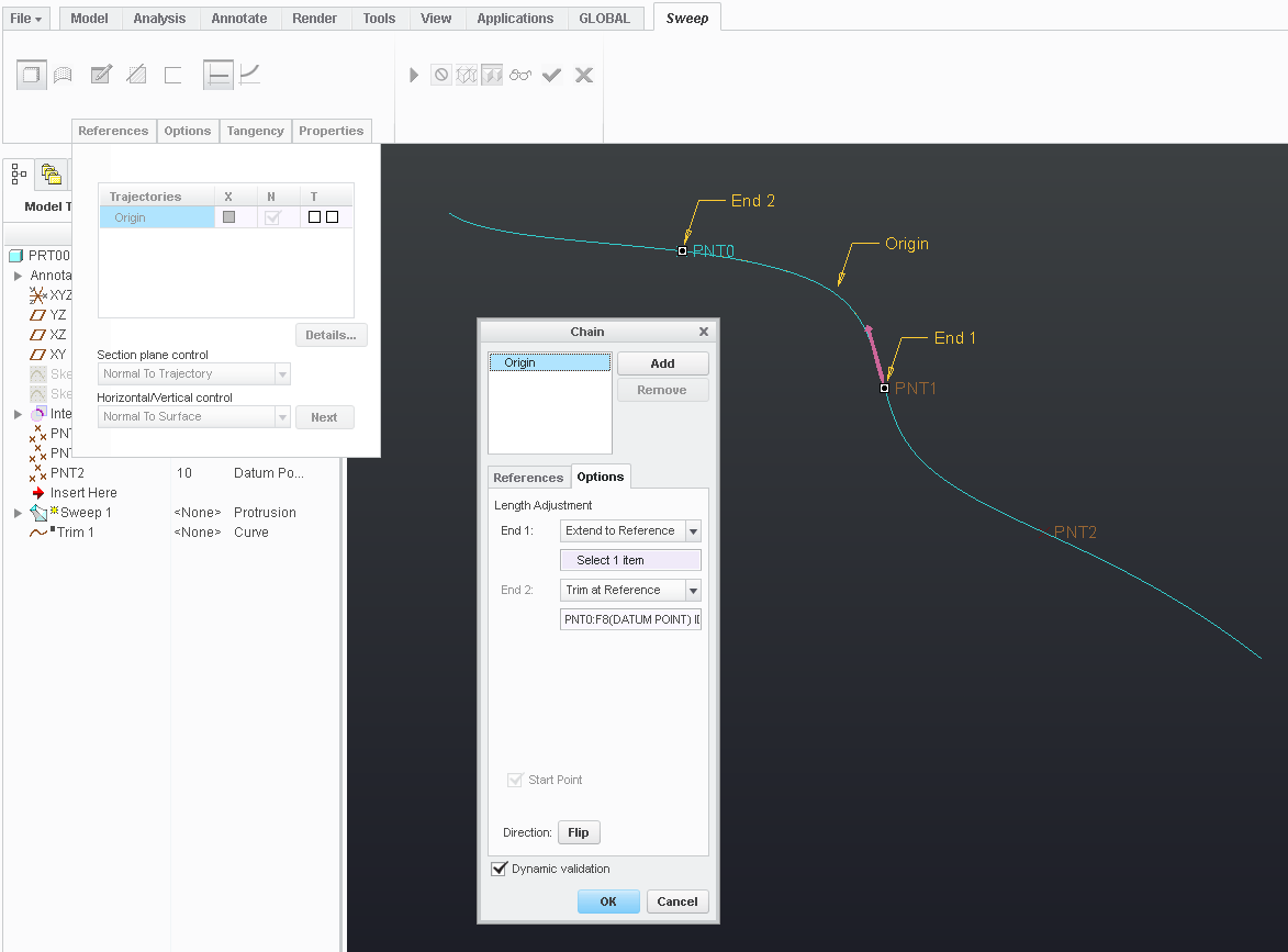
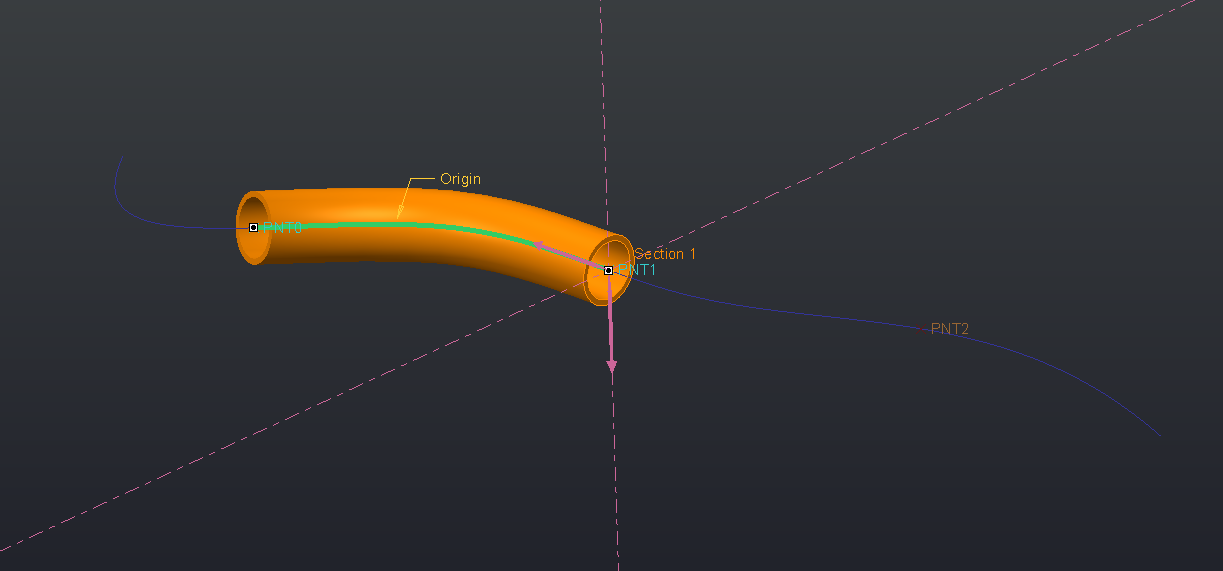
Another method is to trim the curve "on-the-fly". Let's say you're going to use the pipe segments in a sweep command. Start by placing the datum points on the curve as before. In the sweep command, select the 3D trajectory and open the trajectory detail window. In the "Options" tab change the end length adjustments from "Value" to " Trim at Reference" and select two of the datum points. Then create the sweep section as usual and repeat for any other segments. I think this method is preferable.
Your success with this depends on how you created the composite 3D curve. You have to make sure arcs in each of the 2D sketches don't intersect. If they do, your composite 3D curve will have sections where they aren't 2D.
You could also just use Pro/Piping.
Jul 13, 2015
01:04 AM
- Mark as New
- Bookmark
- Subscribe
- Mute
- Subscribe to RSS Feed
- Permalink
- Notify Moderator
Please log in to access translation
Jul 13, 2015
01:04 AM
Thanks Andrew, I am exactly looking for the one you have mentioned. I wanted to automate the process of creating the 3D curve. For that reason I am trying to find out any generic method to generate the 3D curve using equations or through piping. Please share if you have any idea. Thanks again for the reply.
