
Turn on suggestions
Auto-suggest helps you quickly narrow down your search results by suggesting possible matches as you type.
Showing results for
Please log in to access translation
Turn on suggestions
Auto-suggest helps you quickly narrow down your search results by suggesting possible matches as you type.
Showing results for
Community Tip - Learn all about PTC Community Badges. Engage with PTC and see how many you can earn! X
- Community
- Creo (Previous to May 2018)
- Creo Modeling Questions
- Deformed shape of a bar in torsion
Translate the entire conversation x
Please log in to access translation
Options
- Subscribe to RSS Feed
- Mark Topic as New
- Mark Topic as Read
- Float this Topic for Current User
- Bookmark
- Subscribe
- Mute
- Printer Friendly Page
Deformed shape of a bar in torsion
Feb 07, 2013
12:24 PM
- Mark as New
- Bookmark
- Subscribe
- Mute
- Subscribe to RSS Feed
- Permalink
- Notify Moderator
Please log in to access translation
Feb 07, 2013
12:24 PM
Deformed shape of a bar in torsion
The following question comes up once every couple of years, so it makes a good blog topic. The question usually goes something like this.
“When I twist a circular shaft, why does Simulate show that its radius grows? It shouldn’t, right?”
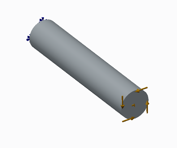
Here’s a picture of a circular shaft that is fixed on one end and with a moment (defined with a total load at point) applied at the other end.
If you run the default static analysis and look at the deformed shape, it looks like the radius grew.
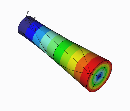
But that can’t be right.
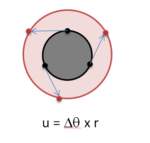
Actually, this is a well-known phenomenon, and is due to the linear approximation used in the default static analysis. In a linear analysis, displacement and rotations are assumed to be small. When rotations are small, the displacement of a point on a disc that rotates is approximately the rotation (measured in radians) multiplied by the distance of the point from the center of rotation. When showing the deformed shape of such a rotation in Simulate, all displacements are exaggerated by scaling.
This figure shows the original shaft in grey. When it rotates, the black points on the boundary of the shaft displace to the red points, giving the illusion that the radius of the shaft grew.
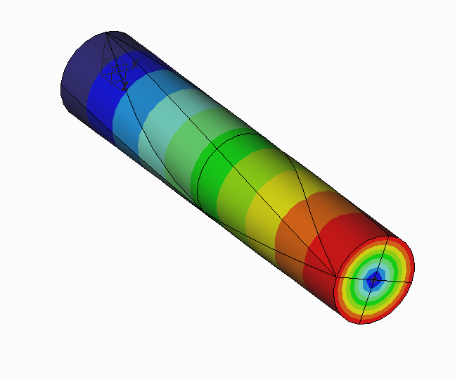
Because large deformation analysis does not make the approximation that displacements and rotations are small, this phenomenon is not present in large deformation analysis, as shown in this deformed of the fringe of the same analysis run with large deformation.
0 REPLIES 0
