
Turn on suggestions
Auto-suggest helps you quickly narrow down your search results by suggesting possible matches as you type.
Showing results for
Please log in to access translation
Turn on suggestions
Auto-suggest helps you quickly narrow down your search results by suggesting possible matches as you type.
Showing results for
Community Tip - You can Bookmark boards, posts or articles that you'd like to access again easily! X
- Community
- Creo (Previous to May 2018)
- Creo Modeling Questions
- Re: How to create a ball joint
Translate the entire conversation x
Please log in to access translation
Options
- Subscribe to RSS Feed
- Mark Topic as New
- Mark Topic as Read
- Float this Topic for Current User
- Bookmark
- Subscribe
- Mute
- Printer Friendly Page
How to create a ball joint
Aug 10, 2010
11:01 AM
- Mark as New
- Bookmark
- Subscribe
- Mute
- Subscribe to RSS Feed
- Permalink
- Notify Moderator
Please log in to access translation
Aug 10, 2010
11:01 AM
How to create a ball joint
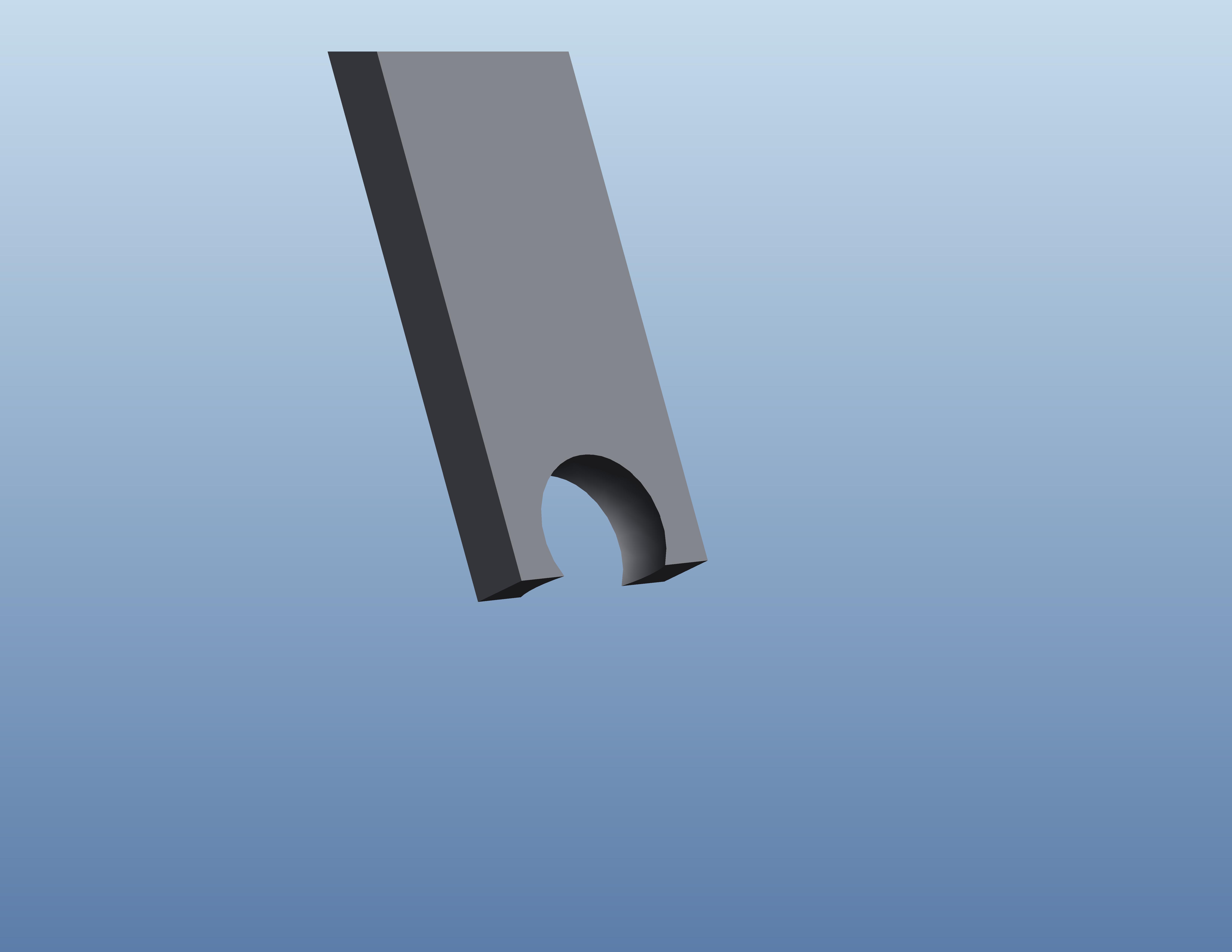
This may be a little difficult to explain but I have two arms that I want to connect with a ball joint. The movement will be up and down, and also swivel 360 degrees. In the first arm I have a spherical cutout where I want to attach the ball, it will be inside that cutout that the ball will move and swivel. How do I or can I constrain a ball inside that cutout to get that sort of movement? I know there is a ball constrain, but I'm not sure how to use it. attached is a picture of the cutout where the ball will be inserted.
Thanks
Solved! Go to Solution.
ACCEPTED SOLUTION
Accepted Solutions
Aug 10, 2010
01:12 PM
- Mark as New
- Bookmark
- Subscribe
- Mute
- Subscribe to RSS Feed
- Permalink
- Notify Moderator
Please log in to access translation
Aug 10, 2010
01:12 PM
By "dummy part" I simply mean that it's not a part of the product design. It's just a utilitarian file. The point and two axes are the features in part C that are used for assembly purposes.
Does that help?
9 REPLIES 9
Aug 10, 2010
11:29 AM
- Mark as New
- Bookmark
- Subscribe
- Mute
- Subscribe to RSS Feed
- Permalink
- Notify Moderator
Please log in to access translation
Aug 10, 2010
11:29 AM
Basically I've controlled the position of Ball Joints using Datum Points. I attach one point on the external of the ball and attach one point on the internal of the cutout. Then I align the points at the assembly and change the position by changing the location of the point internally to the cutout.
The attachement is in WF5 as my example.
Aug 10, 2010
12:08 PM
- Mark as New
- Bookmark
- Subscribe
- Mute
- Subscribe to RSS Feed
- Permalink
- Notify Moderator
Please log in to access translation
Aug 10, 2010
12:08 PM
That makes sense, however it doesn't give you the ability to use the drag function to allow easy maneuverability. Thanks for sending that to me, If I can't find out how to do it the way I'm thinking it should work I'll use your method.
Aug 10, 2010
12:37 PM
- Mark as New
- Bookmark
- Subscribe
- Mute
- Subscribe to RSS Feed
- Permalink
- Notify Moderator
Please log in to access translation
Aug 10, 2010
12:37 PM
Christian,
If I understand correctly, you should be able to accomplish the task by using a "ball" constraint and a "planar" constraint.
I've attached a sample for clarity.
Good luck!
TROY MASON
Impulse Product Development
2445 Directors Row Ste C
Indianapolis, IN 46241
317.243.2225
www.impulseproductdevelopment.com
www.facebook.com/impulseproductdevelopment
Aug 10, 2010
12:49 PM
- Mark as New
- Bookmark
- Subscribe
- Mute
- Subscribe to RSS Feed
- Permalink
- Notify Moderator
Please log in to access translation
Aug 10, 2010
12:49 PM
That is exactly what I was looking for, that answered part of my question, now I'm wondering if it's possible to have that ball not only move up and down in the y plane like it does, but also swivel 360 degrees in the x, z plane?
Aug 10, 2010
12:59 PM
- Mark as New
- Bookmark
- Subscribe
- Mute
- Subscribe to RSS Feed
- Permalink
- Notify Moderator
Please log in to access translation
Aug 10, 2010
12:59 PM
To my knowlege, Pro/E doesn't have the capability, but you could add a 3rd "dummy part" to give you the desired constraints.
The 3rd part (C) would be assembled just like B was in the last assembly. The B is assembled to C with a pin joint or cylinder + planar joint.
New files attached....
Make sense?
Aug 10, 2010
01:07 PM
- Mark as New
- Bookmark
- Subscribe
- Mute
- Subscribe to RSS Feed
- Permalink
- Notify Moderator
Please log in to access translation
Aug 10, 2010
01:07 PM
So when I open up your file in pro E, there is nothing in part C. Or I should say there is no solid model that I can see when I open part C. when you say "dummy part" what exactly do you mean by this?
Aug 10, 2010
01:12 PM
- Mark as New
- Bookmark
- Subscribe
- Mute
- Subscribe to RSS Feed
- Permalink
- Notify Moderator
Please log in to access translation
Aug 10, 2010
01:12 PM
By "dummy part" I simply mean that it's not a part of the product design. It's just a utilitarian file. The point and two axes are the features in part C that are used for assembly purposes.
Does that help?
Aug 10, 2010
01:19 PM
- Mark as New
- Bookmark
- Subscribe
- Mute
- Subscribe to RSS Feed
- Permalink
- Notify Moderator
Please log in to access translation
Aug 10, 2010
01:19 PM
Wow, that's something I would have never thought of. Thanks for your help I really appreciate it!
Aug 10, 2010
01:25 PM
- Mark as New
- Bookmark
- Subscribe
- Mute
- Subscribe to RSS Feed
- Permalink
- Notify Moderator
Please log in to access translation
Aug 10, 2010
01:25 PM
Sure thing! I'm glad I could help.
TROY MASON
Impulse Product Development
2445 Directors Row Ste C
Indianapolis, IN 46241
317.243.2225
www.impulseproductdevelopment.com
www.facebook.com/impulseproductdevelopment
