Community Tip - Stay updated on what is happening on the PTC Community by subscribing to PTC Community Announcements. X
- Community
- Creo+ and Creo Parametric
- 3D Part & Assembly Design
- PCD line in detail drawing.
- Subscribe to RSS Feed
- Mark Topic as New
- Mark Topic as Read
- Float this Topic for Current User
- Bookmark
- Subscribe
- Mute
- Printer Friendly Page
PCD line in detail drawing.
- Mark as New
- Bookmark
- Subscribe
- Mute
- Subscribe to RSS Feed
- Permalink
- Notify Moderator
PCD line in detail drawing.
Hi,
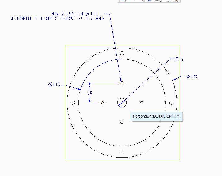
Does anyone know how to make the PCD reference line in detail drawing?

Here is the example of my drawing. I want to do the proper way instead of doing the 26mm dimension.
Thanks.
This thread is inactive and closed by the PTC Community Management Team. If you would like to provide a reply and re-open this thread, please notify the moderator and reference the thread. You may also use "Start a topic" button to ask a new question. Please be sure to include what version of the PTC product you are using so another community member knowledgeable about your version may be able to assist.
- Labels:
-
2D Drawing
- Tags:
- pcd
- Mark as New
- Bookmark
- Subscribe
- Mute
- Subscribe to RSS Feed
- Permalink
- Notify Moderator
Set this in your drawing detail config option (not config.pro):
radial_pattern_axis_circle YES
If the holes were patterned on an axis and created as diameter reference in the model, you should get the BCD centerline.
Please share your file if you are still having trouble with this. It could be how you are modeling the holes if this does not work.
- Mark as New
- Bookmark
- Subscribe
- Mute
- Subscribe to RSS Feed
- Permalink
- Notify Moderator
Hello All,
I am trying to do the same thing as Muhamed, in Creo 3. I cant find the option. Can anyone help?
Or is there an easier way to do this? I don't understand why there isn't an option to add a circular centre line on the drawing.
Does everyone find drawings in Creo much more difficult than other systems or am I still on the learning curve and it will all get easier at some point?
Thanks
- Mark as New
- Bookmark
- Subscribe
- Mute
- Subscribe to RSS Feed
- Permalink
- Notify Moderator
As Antonius answered, you can get the bolt circle centerline if you use a pattern and you have preset the drawing setup option radial_pattern_axis_circle YES.
In the past when making that bolt circle axis, if I couldn't add that option for some reason, I've add a sketch to the model so as to be able to show it.
Nope, Creo is notoriously poor with respect to drawings. I believe they have anticipated for years and years that drawings are going away so why spend any time improving the drawing functionality.
- Mark as New
- Bookmark
- Subscribe
- Mute
- Subscribe to RSS Feed
- Permalink
- Notify Moderator
Hello Stephen,
That works, I hadn't found the drawing Set up option before. Creo seems to like have different options hidden away!
One thing though when i set it, then save it as current it works for me. But if I go back into the Set Up options again and do a find for it, it reverts it back to No.
But if I just look up the option the list it tells me "Yes"
- Mark as New
- Bookmark
- Subscribe
- Mute
- Subscribe to RSS Feed
- Permalink
- Notify Moderator
Drawing setup options are stored on disk in a text file (much like config options) with a *.dtl extension. You need to set a config option to tell Creo where to find it:
drawing_setup_file full\path\to\setupfile.dtl
That sets the drawings settings for new drawings. Once a drawing is created, it takes on the contents of the *.dtl file and saves those settings inside teh drawing file. Changes to the *.dtl on disk are not propagated to existing drawings unless you manually load the updated file.
If you have more than one DTL file (for metric vs. english drawings, for example), you can set a config option to tell Creo what folder you store them in:
pro_dtl_setup_dir full\path\to\drawing_setup_file\folder
- Mark as New
- Bookmark
- Subscribe
- Mute
- Subscribe to RSS Feed
- Permalink
- Notify Moderator
I have now come to dimension up my drawing and found I can't add a diameter dimension to the circular centre line I created for the PCD.
Is this normal, why would this be?
I have also been shown how to sketch on to the drawing to show the PCD line. Which works, but doesn't link to the geometry so I prefer not to use this method.
- Mark as New
- Bookmark
- Subscribe
- Mute
- Subscribe to RSS Feed
- Permalink
- Notify Moderator
Unfortunately it does not let you select the radial centerlines for dimensioning. If you created your initial hole with a diameter bolt circle dimension, you can show that dimension. That is the best option.


