
Turn on suggestions
Auto-suggest helps you quickly narrow down your search results by suggesting possible matches as you type.
Showing results for
Please log in to access translation
Turn on suggestions
Auto-suggest helps you quickly narrow down your search results by suggesting possible matches as you type.
Showing results for
Community Tip - Visit the PTCooler (the community lounge) to get to know your fellow community members and check out some of Dale's Friday Humor posts! X
- Community
- Creo (Previous to May 2018)
- Creo Modeling Questions
- Re: Vertical draft of a hole angled 45 degress
Translate the entire conversation x
Please log in to access translation
Options
- Subscribe to RSS Feed
- Mark Topic as New
- Mark Topic as Read
- Float this Topic for Current User
- Bookmark
- Subscribe
- Mute
- Printer Friendly Page
Vertical draft of a hole angled 45 degress
Jun 07, 2013
06:31 AM
- Mark as New
- Bookmark
- Subscribe
- Mute
- Subscribe to RSS Feed
- Permalink
- Notify Moderator
Please log in to access translation
Jun 07, 2013
06:31 AM
Vertical draft of a hole angled 45 degress
Hi.
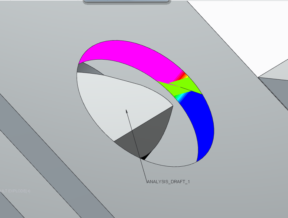
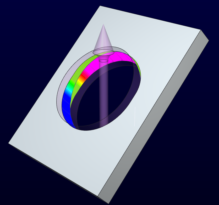
I want to make a hole that is angled 45 degress in a mould opening vertically. I have tried to sketch below how I imagine the mould parts to look like.
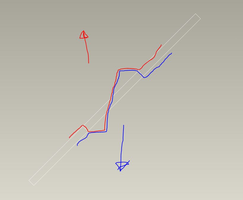
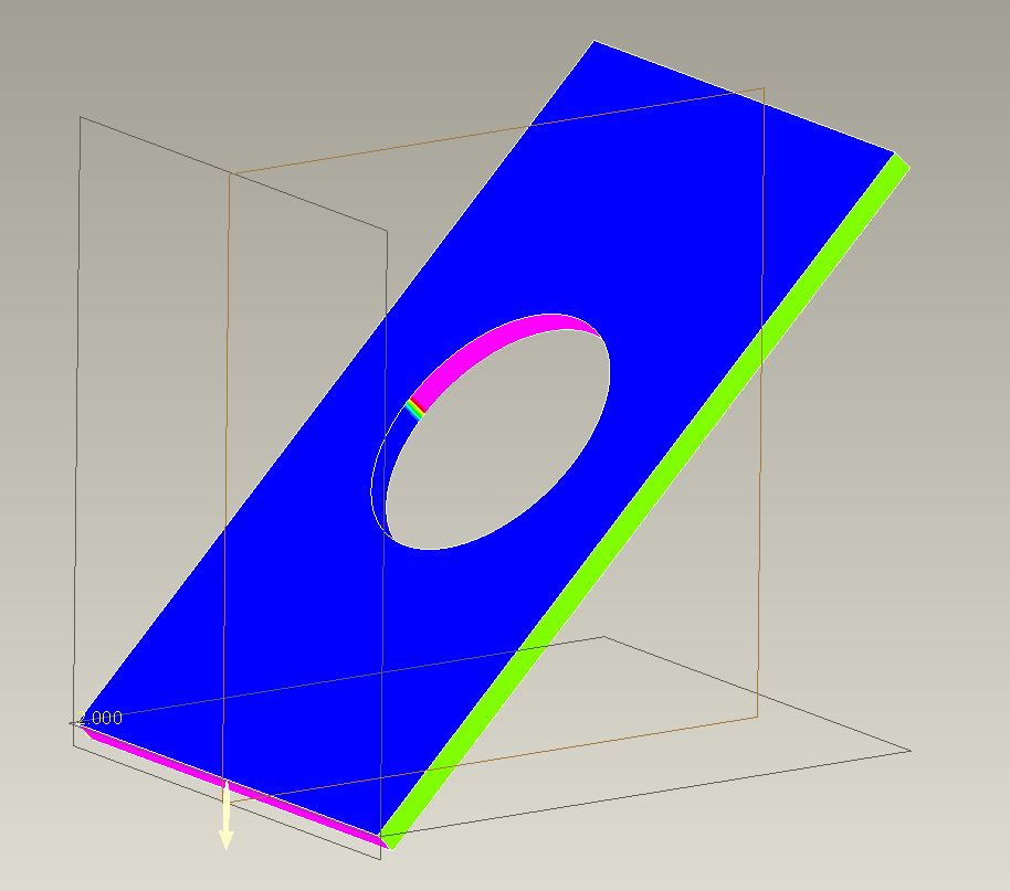
When doing a draft analysis it looks almost fine. I just need to get rid of the "rainbow" area in the middle and have a "clean cut" going from blue to pink with no transisition.
Any good ideas on how to do that?
37 REPLIES 37
Jun 07, 2013
08:04 AM
- Mark as New
- Bookmark
- Subscribe
- Mute
- Subscribe to RSS Feed
- Permalink
- Notify Moderator
Please log in to access translation
Jun 07, 2013
08:04 AM
Hi Esben...
I see what you're tyring to do and it should be possible. The obvious issue is where the two "cuts" meet. There's an oddball transition which is what's showing up as the rainbow on the draft analysis.
You may be able to do this another way- but the first thing I would try is to create a solid volume (using surfaces) that represent the material you're trying to remove. Instead of creating the hole, create surfaces that will be "subtracted" from the solid blue plate thus creating the hole.
The idea here is that you can't really see why the cut is making that rainbow area.. but by trying to model the core or cavity you're trying to remove, it will become clear. I suspect if you used two surface (not solid) revolves, you'll see where the problem lies. I suspect there's some overlapping geometry that must be dealt with. Again, modeling the core will make it clear.
Once you understand where the problem is coming from, you can correct it or mitigate it somehow. If you can create the cavity as a surface, you can then use it to cut away the solid plate. Or, you can simply use the knowledge gained from your surface model to help you better understand how to create the hole with more traditional means.
If you don't get what I'm saying, let me know. Good luck!
Thanks...
-Brian
Jun 07, 2013
01:19 PM
- Mark as New
- Bookmark
- Subscribe
- Mute
- Subscribe to RSS Feed
- Permalink
- Notify Moderator
Please log in to access translation
Jun 07, 2013
01:19 PM
Yep, Brian is right. This is the common issue where people cannot visualize the transition in the die.
The obvious is that where the rainbow resides, you need a small draft from vertical. It will not be a true circle on one side or the other, or both if the transition is in the middle of the "hole".
But, this is not the common way of creating this feature. Depending on your flash tolerance, you could come up from one side and stop at the plane or just beyond it into the mating die. It would be a very odd hole that way, however. it could be done with a slide if it was critical enough.
But to make what you are making, do as Brian suggests. Make a die in the shape of your 1st sketch, square even. Then make it round with a cut the way you want it. Now you will have the edges where your transition will be. Merge>subtract this die from the part (assembly the part/assemble the die/merge-remove the die from the part).
I'll see a bout making a quick model of this. What version are you on?
Jun 07, 2013
03:29 PM
- Mark as New
- Bookmark
- Subscribe
- Mute
- Subscribe to RSS Feed
- Permalink
- Notify Moderator
Please log in to access translation
Jun 07, 2013
03:29 PM
Let's see if this helps.
There is nothing easy about manually making dies for injection molding or die casting. This was a good challenge none the less. The custom made extensions for doing this in Creo work the same way (extensive use of merge features). In this case, I was very deliberate with some of my choices. This is key to understand how you wish to attack each case.
In this case I used the following assumptions:
- I want a perfect circle on both sides of the sheet
- The circle is the same size on both sides (no draft offset)
- No textures will be present within the hole
- Minimal zero draft is allowed
- No slides
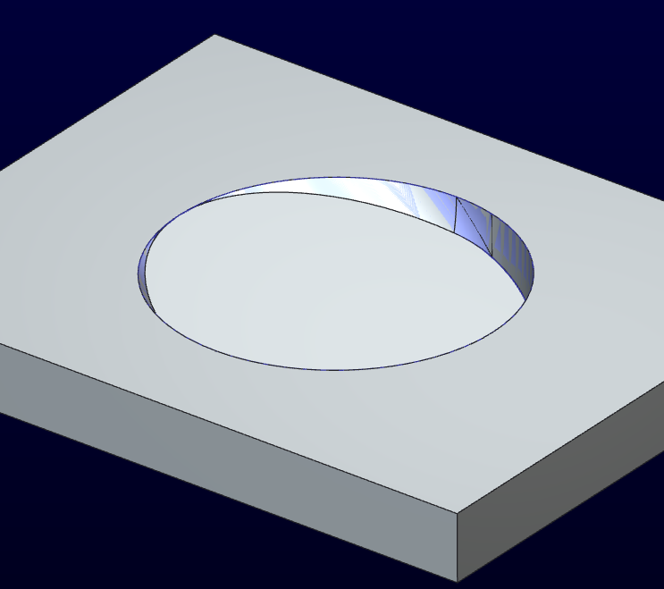
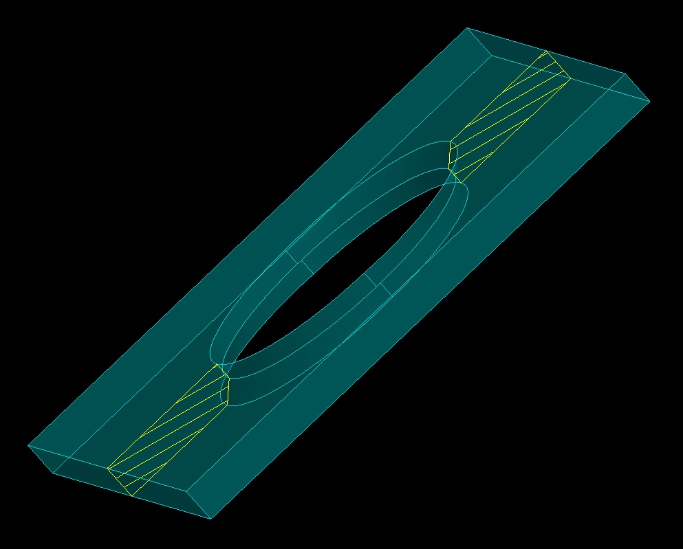
So this is what I came up with:
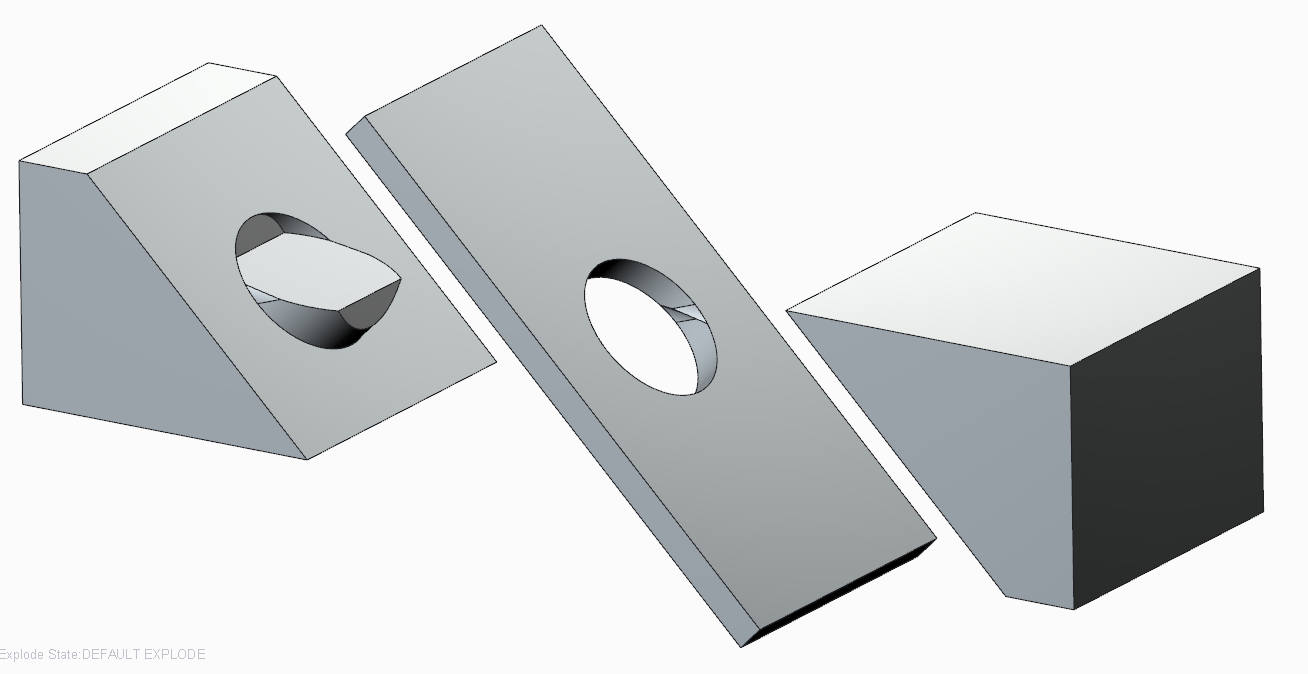
I used a series of sweeps to match ~95% of the circle perfectly (the part that has significant draft naturally).
I used the merge/cut-out feature to create the hole in the sheet. Personally, I don't like using separate dependent files, but there you go. Now that I have a good visual, I -might- be able to do this ends remove the die's merge features on the work part. Everyone has their own comfort level.
Now if I did this in the sheetmetal module, I might make the die on the fly using the surfaces. Although I prefer modeling with solid features, to make the female cavity in the die I had to merge surfaces and solidify them.
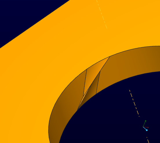
Although the questionable region looked small, it actually has negative draft that is rarely allowed although there are cases that this is done on purpose. In general, bad idea. See where the die transition must happened:
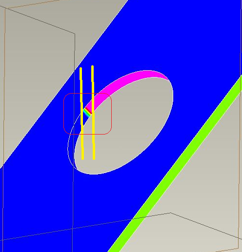
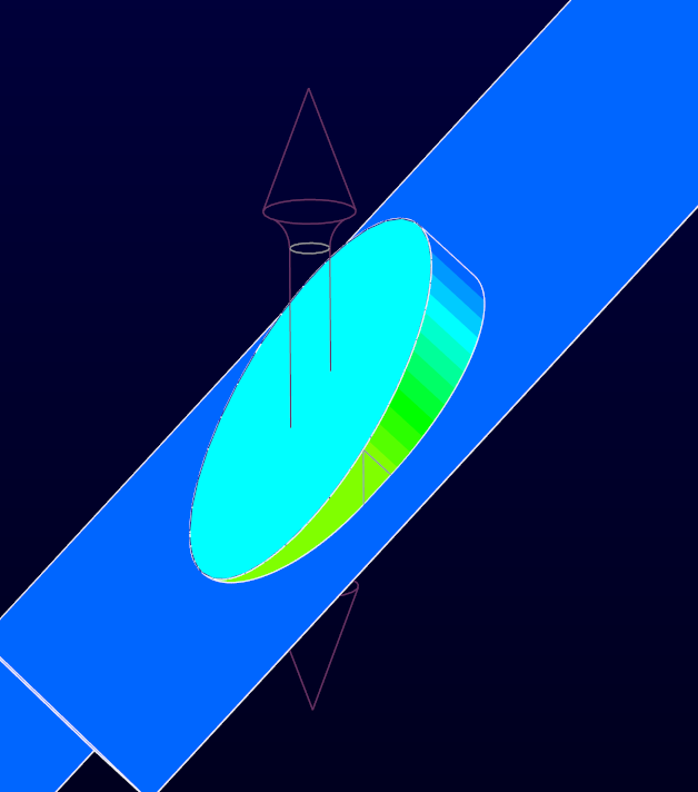
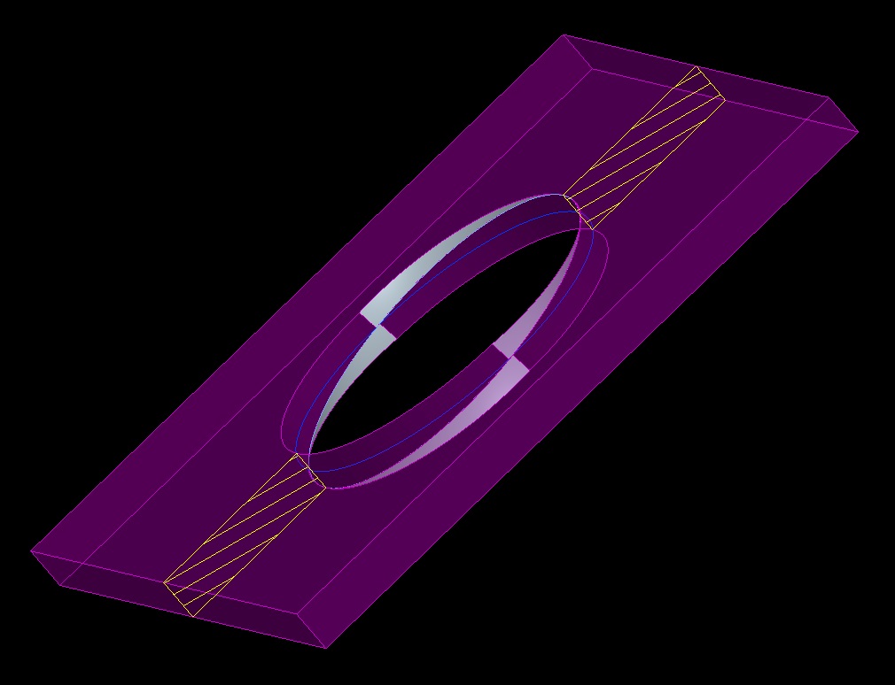
I assumed a 10 degree die transition angle (mating faces of the die); 2.5 degree standard draft on the part. the orange transition in the next image is well on the way to 2.5 degrees. the green is the 0-draft region necessary to meet my "perfect circle" goal.
Here you see the analysis on the die (both dies are identical)
The green triangle is the region created as a divergence of 2 sweeps. The majority of the circle sweep is normal to the curve (the scribed circle), but the transition was swept at a normal of the pull direction. This is how the undercut was avoided.
If you have the full version of Creo 2 (not academic), I can provide the parts to see how I got there. I need to do some cleanup as I got a bit messy for my own tastes. I tried quite a few iterations to get to this result. This one was the most straight forward approach.
Jun 07, 2013
04:24 PM
- Mark as New
- Bookmark
- Subscribe
- Mute
- Subscribe to RSS Feed
- Permalink
- Notify Moderator
Please log in to access translation
Jun 07, 2013
04:24 PM
Antonius you've really come along as a contributor to PTC Community. Really excellent work!
Jun 07, 2013
05:26 PM
- Mark as New
- Bookmark
- Subscribe
- Mute
- Subscribe to RSS Feed
- Permalink
- Notify Moderator
Please log in to access translation
Jun 07, 2013
05:26 PM
 That's what happens when you have too much time on your hands.
Attached is a clean version of the files:
Jun 13, 2013
09:49 AM
- Mark as New
- Bookmark
- Subscribe
- Mute
- Subscribe to RSS Feed
- Permalink
- Notify Moderator
Please log in to access translation
Jun 13, 2013
09:49 AM
Interesting discussion and creative solution, Antonius.
I'd like to add a couple things.
- The problem isn't simply that you have a 'rainbow' area, it's that that transition from A side to B side isn't aligned with your pull direction. This creates, as Antonius discovered, undercuts on both sides of the circle.
- I don't think you need the protruding slide-by shut off, the P/L can be right on the face of the part on each side.
- By creating this so that you have a true circle on both sides, you do not have a true thru diameter as material must be added inside the hole to make the part moldable.
- With a small bit of surfacing, what Antonius has done can all be done natively in the part which makes the database simpler and keeps all the design dims in the part
- If having a circular profile is only important on one side or the other, or even in the center, this can be made quite simply with an extrude and no slide-by shutoffs.
I've uploaded a zip file showing how to create options 4 & 5 in Creo2.
Jun 13, 2013
01:00 PM
- Mark as New
- Bookmark
- Subscribe
- Mute
- Subscribe to RSS Feed
- Permalink
- Notify Moderator
Please log in to access translation
Jun 13, 2013
01:00 PM
Doug, you are right that approximations are easier to model and certainly easier to manage.
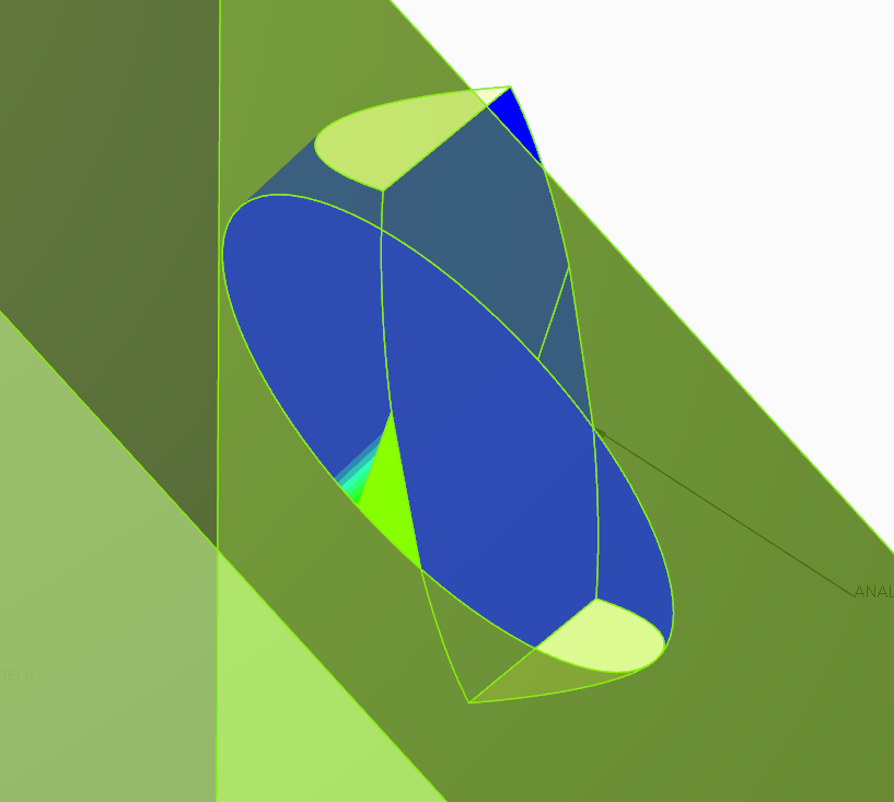
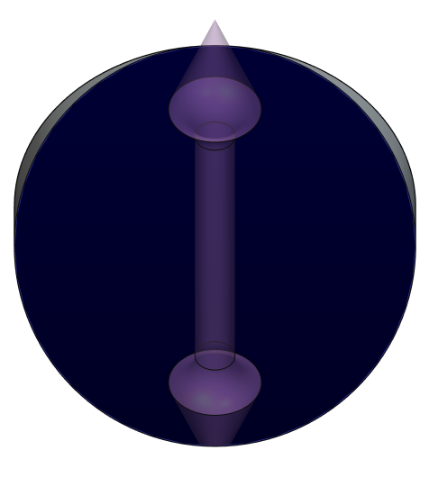
Do an analysis on on your simple version. You will still find negative draft in those 2 files. I was working on a similar version to simple_2 where the parting was through the hole at opposite end (skewed oval through the center; image below). It became quite complex from a modeling perspective fairly quickly as I ended up with the dreaded tangent convergence that virtually all CAD systems choke on.
Also check the boundary blend version. Although it works very much the same, it is still slightly different than the straight forward die version. The remaining interference is slightly less in the version provided. Again, it all depends on the assumption you have to apply to the design intent. I've never been one to "approximate" what I hand a machinist. I much prefer providing true intent.
Below is that alternate. Although I could make the surface to close the transition gap, due to the tangent interface on the shallow end, I could not get it to solidify. Same old problem. But the idea is sound for a simplified die.
Most likely... since the hole is on a high angle, the machinist wouldn't care about the higher post. He/she is machining the face anyway and has plenty of material to make the posts. Why not make the best feature possible. Again... not knowing design intent, it is hard to argue the engineer's choice of requirements.
Jun 13, 2013
02:46 PM
- Mark as New
- Bookmark
- Subscribe
- Mute
- Subscribe to RSS Feed
- Permalink
- Notify Moderator
Please log in to access translation
Jun 13, 2013
02:46 PM
I did a little more work on the alternative hole.
New assumptions:
- Through hole perfectly round at face angle.
- Minimize deformation at surface
- No negative draft permitted
- Zero draft permitted on a limited basis
- No texture in the hole
In this case, the draft is offset immediately at separation due to the high draft on the opposite face. Still more zero-draft than the original so total zero-draft analysis of the mold must be considered. No surfaces or approximations.
No separate die file ...but the work was duplicated for each half. Maybe rotational patterning would save some effort. A lot of prep work for related features. A bit more effort would reduce the feature count. A little more relation work and the hole is easily scalable (think UDF).
Creo 2.0 and STEP attached
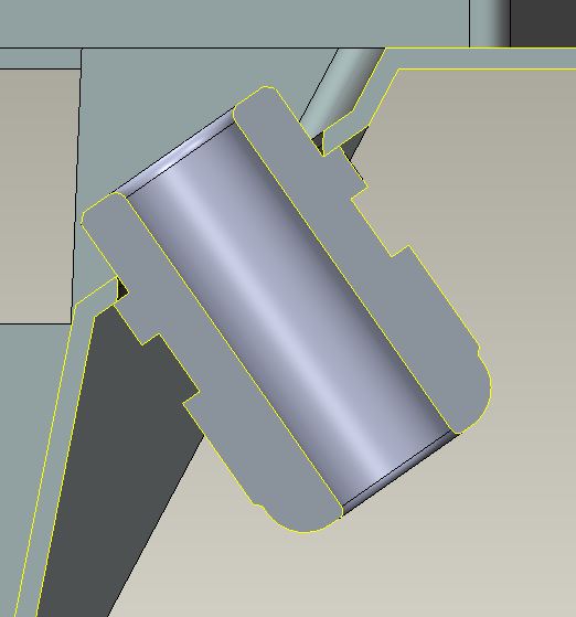
Physical tooling view (reference - not required in model):
Jun 13, 2013
05:52 PM
- Mark as New
- Bookmark
- Subscribe
- Mute
- Subscribe to RSS Feed
- Permalink
- Notify Moderator
Please log in to access translation
Jun 13, 2013
05:52 PM
Nice work Antonius!
Jun 13, 2013
03:54 PM
- Mark as New
- Bookmark
- Subscribe
- Mute
- Subscribe to RSS Feed
- Permalink
- Notify Moderator
Please log in to access translation
Jun 13, 2013
03:54 PM
Good catch on the undercuts in the simple versions, they do require a bit more work to eliminate them. Additionally, you'd need to add draft to the extruded surfaces to eliminate the zero draft conditions.
It really depends on what the hole is for, what (if anything) needs to pass through the hole and what the aesthetic requirements of the hole are. There are all sort of concepts available, as illustrated in this thread, to get a moldable opening, it just depends on what you can live with.
I agree with the idea of not making approximations on what you want in the CAD file. Give the toolmaker exactly what you want, in this case you are going to need to decide what compromises you can live with to get the geometry in moldable form, then model that.
(and then send it to China and they'll do whatever they want.)
Jun 13, 2013
10:15 AM
- Mark as New
- Bookmark
- Subscribe
- Mute
- Subscribe to RSS Feed
- Permalink
- Notify Moderator
Please log in to access translation
Jun 13, 2013
10:15 AM
Nice work Antonius!
My question to Esben is why make it so complicated? You could WAAAAY more easily (and cheaply) put the shape required for the hole in one side, or, if you wanted to split the draft, put the parting line in the middle of the thickness. What you're doing REALLY complicates everything.
Is there a reason this absolutely has to be done like this?
Jun 14, 2013
03:44 AM
- Mark as New
- Bookmark
- Subscribe
- Mute
- Subscribe to RSS Feed
- Permalink
- Notify Moderator
Please log in to access translation
Jun 14, 2013
03:44 AM
Hi all.
First of all thanks for your help and the attached files. It makes it really easy to understand what you mean.
I'm amazed by the quality of the answers.
Then I must say this solution is a bit more complex than imagined.
To put it into a context. A strain relief has to go through the hole, and I really can't allow much tolerance in order to keep it tight. I tried quickly to split the draft in the middle of the thickness, but I think the gaps are to big.
I think Doug's solution 4 will work quite well, though.
But again as said previously, I'm maybe doing it way more complex than it has to be. Just can't see how to simplify it when I can't allow too big gaps, other than using some side actions, which also is an option.
If you have any great ideas, feel free to write'em here
Jun 14, 2013
09:33 AM
- Mark as New
- Bookmark
- Subscribe
- Mute
- Subscribe to RSS Feed
- Permalink
- Notify Moderator
Please log in to access translation
Jun 14, 2013
09:33 AM
I'm sure you already looked into if you can change the angle of the mounting surface, that would help a lot if you could get it closer to horizontal. 
You can take that #4 and move the P/L sketch so that the left side is close to the bottom and the right is close to the top to get as much 'true diameter' as possible. It doesn't need to be parallel to the wall.
Good luck.
Jun 14, 2013
10:35 AM
- Mark as New
- Bookmark
- Subscribe
- Mute
- Subscribe to RSS Feed
- Permalink
- Notify Moderator
Please log in to access translation
Jun 14, 2013
10:35 AM
Since this is a nut'd assembly, perfect roundness is likely not required. I would suggest a thickness change (shoulder) or a few gussets in this region as the application could see some significant stresses when you add a cable.
I would also suggest asking your toolmaker what the preference is based on overall complexity. Some options are easier to fabricate.
And if you have more through-features at this angle, a slide may be appropriate. Again, a review with the toolmaker can really pay off in both CAD effort and final tooling costs.
Jun 14, 2013
10:24 AM
- Mark as New
- Bookmark
- Subscribe
- Mute
- Subscribe to RSS Feed
- Permalink
- Notify Moderator
Please log in to access translation
Jun 14, 2013
10:24 AM
Esben,
How do you intend to fix that insert (strain relief), the wall thickness is not enough?
Or is the strain relief located in a different mating product?
Like Doug said, try to see if you can place it horizontal, can't you break the surface or do you need to follow this line?
Sorry I tried to upload a picture, but I could not submit the post
Cheers,
Alain
Jun 14, 2013
06:28 PM
- Mark as New
- Bookmark
- Subscribe
- Mute
- Subscribe to RSS Feed
- Permalink
- Notify Moderator
Please log in to access translation
Jun 14, 2013
06:28 PM
Ok, so, here's my simplified take on this:
The parting line/shutoff is extremely easy, simple, and cheap: It's flat, halfway thru the part, parallel to the surfaces you'll mate against. On either top or bottom end (in the pic), you get 1/2 the material thickness to locate the strain relief. In the center you get the whole thickness. I added 1deg of draft in the pull direction (normal to the top plane) for sheyts and giggles. From what I saw of your needs, I think this will work just fine. If you absolutely HAD to have the circle as close as possible, then Anonius's solution is what you want. It all depends on your needs.
I've included the part as well.
Have fun with it!
Jun 14, 2013
07:32 PM
- Mark as New
- Bookmark
- Subscribe
- Mute
- Subscribe to RSS Feed
- Permalink
- Notify Moderator
Please log in to access translation
Jun 14, 2013
07:32 PM
Here's another take on it. Very similar to what Antonius did in the "silver" model (from the pic, I can't open the models). This gives a very close approximation of the hole, with a slightly more complicated shutoff. It's funny, I first didn't understand why it "lobed" the hole (as it did in his pics too), then I realized what the VSS was doing, and think it did exactly as asked.
Jun 15, 2013
01:22 AM
- Mark as New
- Bookmark
- Subscribe
- Mute
- Subscribe to RSS Feed
- Permalink
- Notify Moderator
Please log in to access translation
Jun 15, 2013
01:22 AM
Nice Sweep,
Jun 16, 2013
03:45 AM
- Mark as New
- Bookmark
- Subscribe
- Mute
- Subscribe to RSS Feed
- Permalink
- Notify Moderator
Please log in to access translation
Jun 16, 2013
03:45 AM
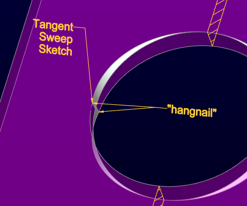
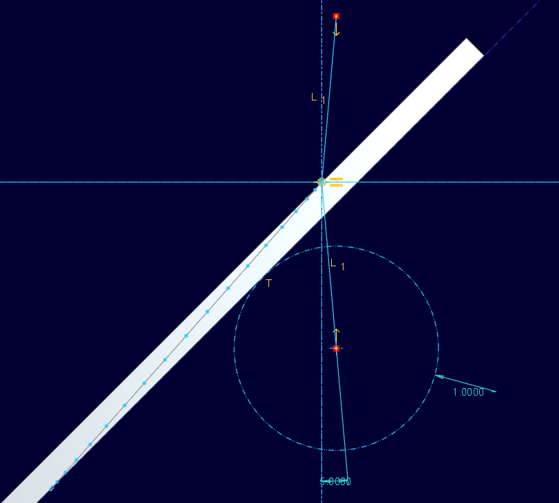
I was intrigued by this method for getting draft included and it worked great with the sweep. Once merged with the extrude, it leaves a little "hangnail"... a non-tangent transition between the ellipse and the circle along the edge. I created a sketched line to create the tangency on the surface and used it for a VSS between the line (origin) and the parting line ellipse (chain1). I drew a line in the section between the two "x"'s (trajectory intersections) and let it trim out that small triangle. Beautiful results as the sweep trajectory (origin) is not quite vertical so the "normal extrude" semi-circle, without draft provides nearly the same draft as the selected draft for the other half of the cut.
And yes, getting that little sketch to behave tangent to the reference can be tricky, but it works.
This is indeed a great way to ensure draft on all faces of this type of feature. ...until such time that we can extrude in a direction other than normal, that is. How is that feature coming along, PTC? 
Here's another take on it. Very similar to what Antonius did in the "silver" model (from the pic, I can't open the models). This gives a very close approximation of the hole, with a slightly more complicated shutoff. It's funny, I first didn't understand why it "lobed" the hole (as it did in his pics too), then I realized what the VSS was doing, and think it did exactly as asked.
Jun 17, 2013
10:48 AM
- Mark as New
- Bookmark
- Subscribe
- Mute
- Subscribe to RSS Feed
- Permalink
- Notify Moderator
Please log in to access translation
Jun 17, 2013
10:48 AM
What I found funny, and almost missed, was that it missed taking out the material in the upper right "lobe"/corner. I had to mirror a surface and use that to trim it. Was that the "hangnail" you mentioned? I almost missed it, it was so slight. Weird how sometimes Pro/E will do things like that. Like, a round works on one side of a symmetric part, but will NOT work on the other side.
I was struggling to get the draft to work, so I used a VSS, and built in 1 deg of draft. I didn't have time to do a draft analysis yet but I'm going to check it. since I used the axis to measure the 1deg from, there should be an even 1 deg draft in the pull direction.
Jun 17, 2013
11:13 AM
- Mark as New
- Bookmark
- Subscribe
- Mute
- Subscribe to RSS Feed
- Permalink
- Notify Moderator
Please log in to access translation
Jun 17, 2013
11:13 AM
Hangnail....
My initial sweep includes the draft in both directions. Constant normal to the pull direction.
The second extrude is along the hole direction (45 degrees), no draft, and extruded to the vertical (pull direction) plane to protect the already established surface.
A bit more work let me do a fully scalable version including the trimming of the hangnail. But I concur; all too often a mirrored/patterned feature simply fails and often fails scalability.
For Creo 2 people: See attached
BTW, ... how do you manage doing stuff when you layer hide things all the time. UHHHGGGGG! I start with empty part just so - I - have control of the layers
Jun 17, 2013
11:55 AM
- Mark as New
- Bookmark
- Subscribe
- Mute
- Subscribe to RSS Feed
- Permalink
- Notify Moderator
Please log in to access translation
Jun 17, 2013
11:55 AM
This one seems to tie Pro/E in knots. I tried draft.....and it fails, though the preview shows what I want. I tried making a surface, then drafting that along the hinge curve, and that works.....but when I solidify it to use as a cut it only does the bottom half.....yet if I flip the direction it works fine......HUH????? I think the VSS gives slightly distorted results, as the line isn't perfectly 1 deg from the axis used. I think this behavoir is a bug.
Does the hangnail interfere with pulling of the mold? I wouldn't think so, the draft looked ok to me. I mean, a boundary blend can be put in to make things nice and smooth if needed, I just didn't have time to take it past getting the draft to work.
Edit: Ok, update on draft on the surface I used to solidify/cut: When I tried to split the draft, it didn't work right. I used one-sided draft, and it acted like a split draft!
Jun 17, 2013
12:07 PM
- Mark as New
- Bookmark
- Subscribe
- Mute
- Subscribe to RSS Feed
- Permalink
- Notify Moderator
Please log in to access translation
Jun 17, 2013
12:07 PM
Nope, the hangnail didn't cause a draft issue. Just a hard thing to machine in the negative.
I had all kinds of issues making that initial cut. I am not using any guide chains as these are what cause the most trouble where the circle and ellipse go tangent.
Jun 17, 2013
12:27 PM
- Mark as New
- Bookmark
- Subscribe
- Mute
- Subscribe to RSS Feed
- Permalink
- Notify Moderator
Please log in to access translation
Jun 17, 2013
12:27 PM
Yeah, this seems like a simple thing, but it's giving Pro/E fits. That draft issues I ran into was weird.......
Jun 17, 2013
12:38 PM
- Mark as New
- Bookmark
- Subscribe
- Mute
- Subscribe to RSS Feed
- Permalink
- Notify Moderator
Please log in to access translation
Jun 17, 2013
12:38 PM
I changed your version by changing the angle to 5; Normal to projection (selected pull direction Y-axis); solid and remove material; VSS became optional; flip direction. It would not preview a solid, but it did do the remove.
Jun 17, 2013
12:45 PM
- Mark as New
- Bookmark
- Subscribe
- Mute
- Subscribe to RSS Feed
- Permalink
- Notify Moderator
Please log in to access translation
Jun 17, 2013
12:45 PM
Okay, I take it back... there was a fail in the change. I needed to move the start of the sweep to the "top" (other side) or it would completely skip one fo the 4 cuts.
Jun 17, 2013
01:32 PM
- Mark as New
- Bookmark
- Subscribe
- Mute
- Subscribe to RSS Feed
- Permalink
- Notify Moderator
Please log in to access translation
Jun 17, 2013
01:32 PM
Weird results, huh?
Jun 17, 2013
01:39 PM
- Mark as New
- Bookmark
- Subscribe
- Mute
- Subscribe to RSS Feed
- Permalink
- Notify Moderator
Please log in to access translation
Jun 17, 2013
01:39 PM
Scary! I also noticed that your cross section doesn't show up in the model tree no matter what I do. I would never have known it was there unless I made a drawing. Normally, in Creo, they exist in a footer.
Jun 17, 2013
03:52 PM
- Mark as New
- Bookmark
- Subscribe
- Mute
- Subscribe to RSS Feed
- Permalink
- Notify Moderator
Please log in to access translation
Jun 17, 2013
03:52 PM
Well, for the most part, I always use internal sketches unless I use a sketch for multiple parts in an assembly or multiple features in a part or family table of parts. But it doesn't even show up in the footer of the feature? Hmmmm....
This one definately has some weird results.........
