
Turn on suggestions
Auto-suggest helps you quickly narrow down your search results by suggesting possible matches as you type.
Showing results for
Please log in to access translation
Turn on suggestions
Auto-suggest helps you quickly narrow down your search results by suggesting possible matches as you type.
Showing results for
Community Tip - Did you know you can set a signature that will be added to all your posts? Set it here! X
- Community
- Creo (Previous to May 2018)
- Creo Modeling Questions
- Re: gtol placement
Translate the entire conversation x
Please log in to access translation
Options
- Subscribe to RSS Feed
- Mark Topic as New
- Mark Topic as Read
- Float this Topic for Current User
- Bookmark
- Subscribe
- Mute
- Printer Friendly Page
gtol placement
Mar 29, 2016
08:06 AM
- Mark as New
- Bookmark
- Subscribe
- Mute
- Subscribe to RSS Feed
- Permalink
- Notify Moderator
Please log in to access translation
Mar 29, 2016
08:06 AM
gtol placement
Hi,
I'm looking for a way to place gtols in like the one in the picture. Have been looking for this a long time, but never found how to do it.
Picture is a bit fuzzy, but you get the gist of it, right? I want to link the gtol directly to the reference.
- Tags:
- gtol
- gtol placement
7 REPLIES 7
Mar 29, 2016
08:39 AM
- Mark as New
- Bookmark
- Subscribe
- Mute
- Subscribe to RSS Feed
- Permalink
- Notify Moderator
Please log in to access translation
Mar 29, 2016
08:39 AM
The reason you can't do it is because it is no where near ASME practice.
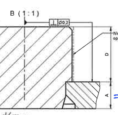
Possibly should look more like this (90 degrees rotated).
Depending on your requirements, you would make the surface on the A dimension as datum A and the you would hold your axis (pin or hole) perpendicular to that surface (image below). Or opposite, you would set your axis (pin or hole) to datum A and then hold the surface to be perpendicular to the datum.

Mar 29, 2016
08:56 PM
- Mark as New
- Bookmark
- Subscribe
- Mute
- Subscribe to RSS Feed
- Permalink
- Notify Moderator
Please log in to access translation
Mar 29, 2016
08:56 PM
It was allowed at one time but discontinued at some point not sure when. I've only seen it once and it was on a drawing from the late 1980's.
Mar 31, 2016
05:59 AM
- Mark as New
- Bookmark
- Subscribe
- Mute
- Subscribe to RSS Feed
- Permalink
- Notify Moderator
Please log in to access translation
Mar 31, 2016
05:59 AM
As a European Subcontractor we don't really follow the ASME-standard per se.
I still find it a lot on drawings from European clients, and I find it a rather elegant solution.
Doe you know where I can find the ASME-rules concerning drawings?
Mar 31, 2016
06:31 AM
- Mark as New
- Bookmark
- Subscribe
- Mute
- Subscribe to RSS Feed
- Permalink
- Notify Moderator
Please log in to access translation
Mar 31, 2016
06:31 AM
ASME rules pertaining to drawing Geometric Dimensioning and Tolerancing is ASME Y14.5, with 2009 being the latest (this is the only "American Spec" that one needs to qualify by year)
The base ISO is 1101, then "married" with a few others, is brought all together in one way like ISO 2768.
What you are trying to do is an accepted method though I can not cite the specification which allows/describes this practice at this time.
One can see it demonstrated in ISO 2768 part II.
This methodology I have only seen used in the EU (ISO based countries).
Using the ansi.dtl file (former ASME) will not gain you access to what you are trying to accomplish easily.
I do not know if using the ISO version will provide this ability as I have not used it in conjunction with Pro/E (I have with NX)
Perhaps some ISO based colleague can chime in and represent.
Mar 31, 2016
07:51 AM
- Mark as New
- Bookmark
- Subscribe
- Mute
- Subscribe to RSS Feed
- Permalink
- Notify Moderator
Please log in to access translation
Mar 31, 2016
07:51 AM
The problem I have with the GTOL is interpretation. In ASME Y14.5, perpendicularity requires a datum. I can't understand if you want the axis to be perpendicular to the surface or the surface to be perpendicular to the axis.
I was under the impression (possibly wrong) that ISO and ASME had basically agreed on GD&T specification and interpretation. I suppose that if you were redrawing an existing drawing, you could continue to use apply an older standard, but if it's a new drawing, shouldn't it be made to the latest standard?
All that being said, I've fudged tons of GD&T in my career and will probably apply my own standards for the foreseeable future. Sometimes using what your company understand is more vital than being exactly to the latest standard. I really doubt there is a direct way to create the callout within Creo, you'll likely have to sketch it out. If you do this regularly, you should probably create a symbol you can use for your base geometry and then modify for each specific drawing.
Mar 31, 2016
08:34 AM
- Mark as New
- Bookmark
- Subscribe
- Mute
- Subscribe to RSS Feed
- Permalink
- Notify Moderator
Please log in to access translation
Mar 31, 2016
08:34 AM
Steve,
In this case, the base is the axis and the surface is being held perpendicular.
Your impression is correct, you forgot about implementation. With regards to this example, instead of making a separate callout for a datum (axis) as ASME requires, ISO allows the direct "connection" to be made.
You're right, in the end it doesn't matter how it's put on the drawing but how it is understood by both parties (i.e. engineering/mfg).
Its when the parties change that a "standard" understanding will shine.
Mar 31, 2016
09:10 AM
- Mark as New
- Bookmark
- Subscribe
- Mute
- Subscribe to RSS Feed
- Permalink
- Notify Moderator
Please log in to access translation
Mar 31, 2016
09:10 AM
The leader attaches to the datum reference so in what is shown the axis is being held perpendicular to the surface. If it the surface were being held perpendicular to the axis the filled triangle would be attached to the surface and the leader to the axis. In the ISO standard if the tolerance frame can be directly connected with the datum feature by a leader line the datum can be omitted from the frame.
As of 2004 this no longer standard ISO practice.
