
Turn on suggestions
Auto-suggest helps you quickly narrow down your search results by suggesting possible matches as you type.
Showing results for
Please log in to access translation
Turn on suggestions
Auto-suggest helps you quickly narrow down your search results by suggesting possible matches as you type.
Showing results for
Community Tip - Did you know you can set a signature that will be added to all your posts? Set it here! X
- Community
- Creo (Previous to May 2018)
- Creo Modeling Questions
- radius creation
Translate the entire conversation x
Please log in to access translation
Options
- Subscribe to RSS Feed
- Mark Topic as New
- Mark Topic as Read
- Float this Topic for Current User
- Bookmark
- Subscribe
- Mute
- Printer Friendly Page
radius creation
Aug 22, 2014
08:54 PM
- Mark as New
- Bookmark
- Subscribe
- Mute
- Subscribe to RSS Feed
- Permalink
- Notify Moderator
Please log in to access translation
Aug 22, 2014
08:54 PM
radius creation
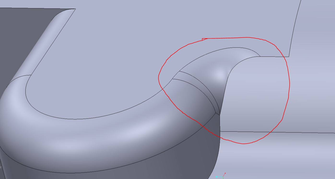
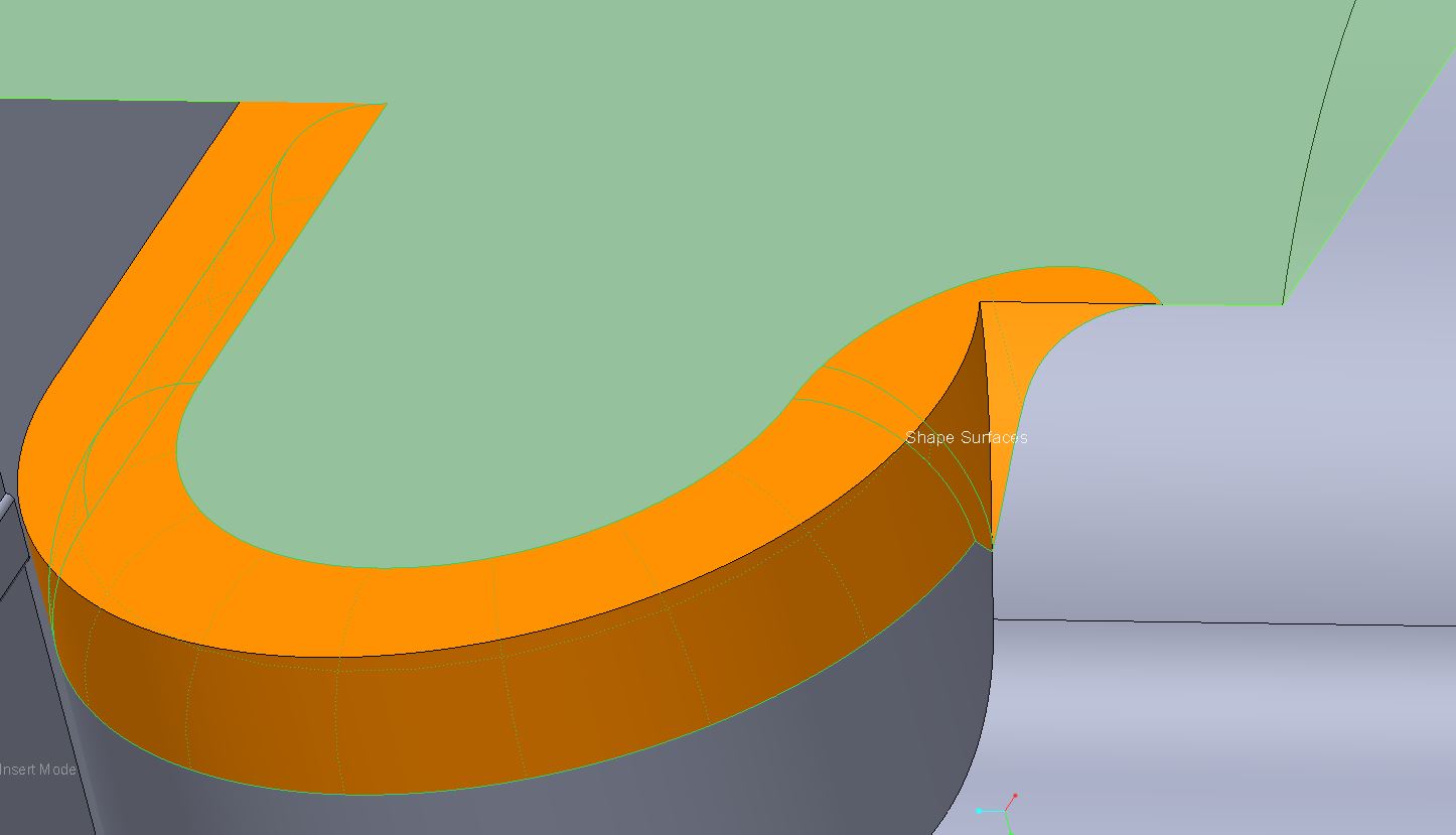
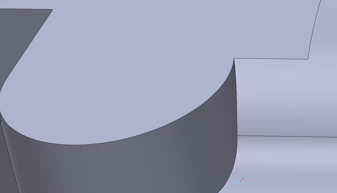
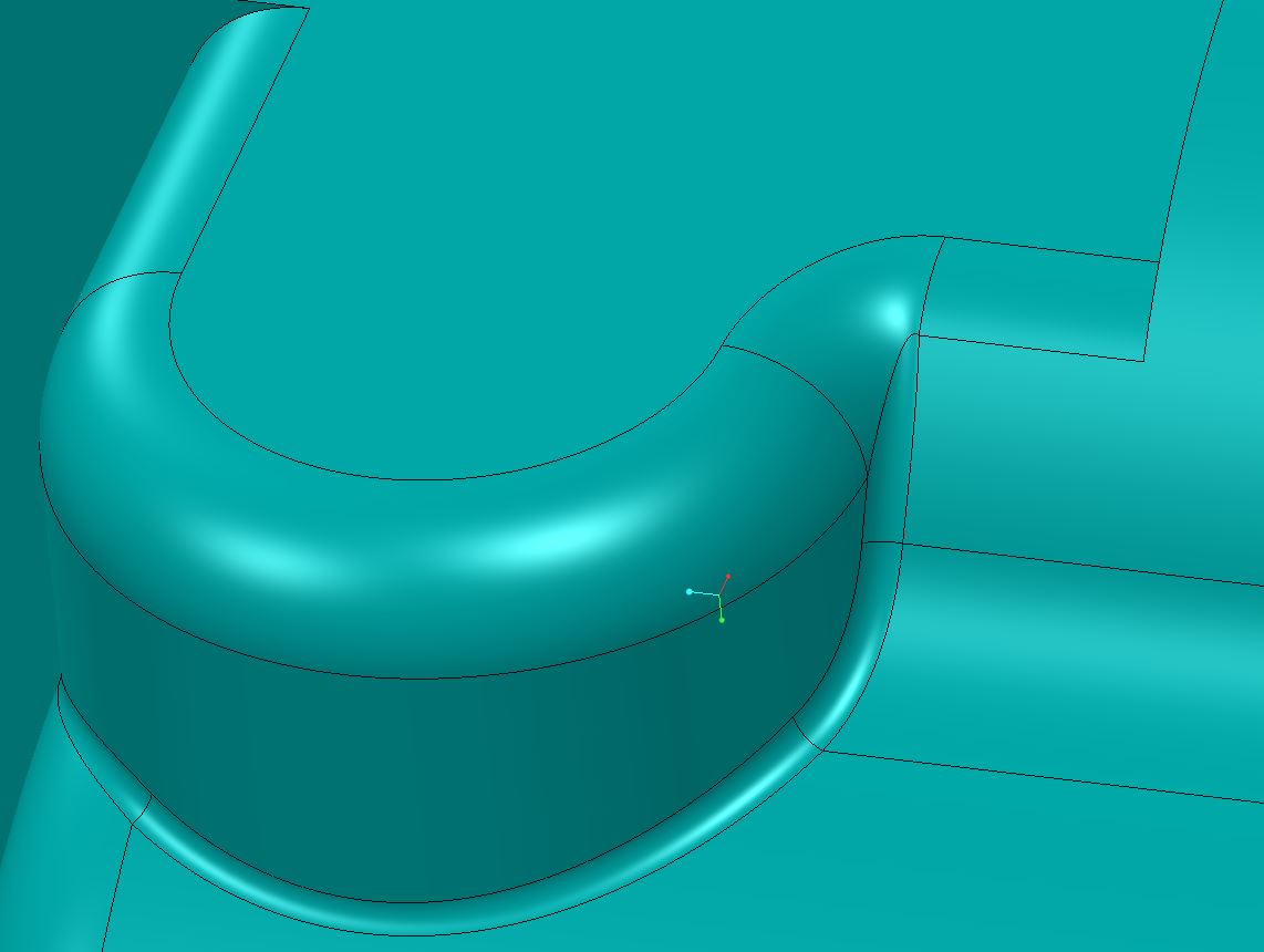
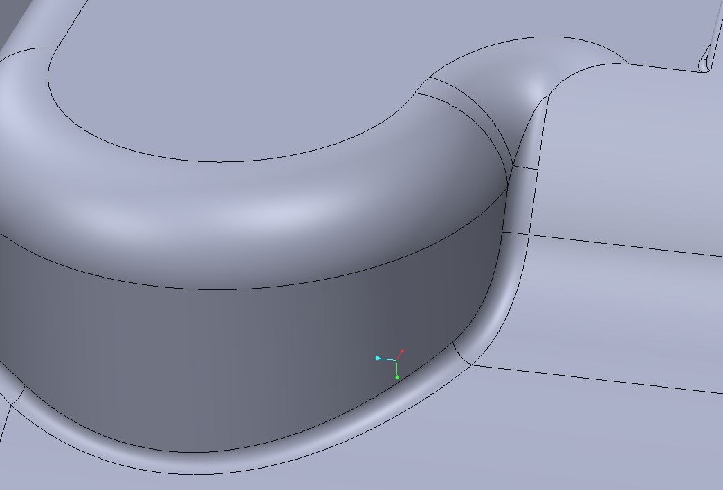
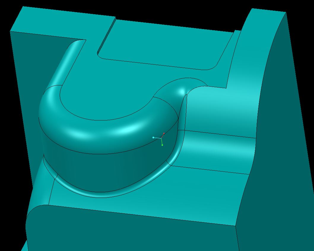
CREO2 M120. remodeling a geographical nightmare that someone created. Pic 1 is what I need to do, pic 2 and 3 is removing it with Flex, Pic 4 is putting it back on with normal radius tool.
And ideas? I thought there was a way in the past to stop radius from being created on tangent chains? maybe that would do it?
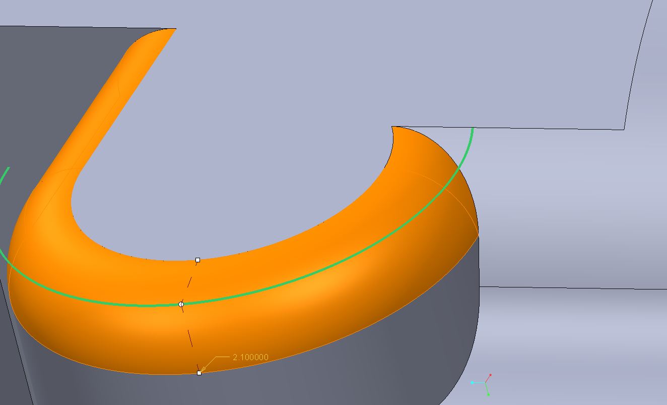
There is also a .5 radius on the lower side, Pic 5, this might be key, too. What I dont have is a good picture of what they look like blended together, although it is amazingly close to Pic 1. (it doesnt wrap around like you would think; it just ends).
Pic 5 the radius isn't supposed to continue to the right. (pic 5 is putting the .5 radius on first.)
15 REPLIES 15
Aug 22, 2014
09:13 PM
- Mark as New
- Bookmark
- Subscribe
- Mute
- Subscribe to RSS Feed
- Permalink
- Notify Moderator
Please log in to access translation
Aug 22, 2014
09:13 PM
One of my early Pro/E failures in a paying contract was managing radii. Although many new buttons were added, it is still a very poor tool with an extremely high CPU overhead. I promise you, SW dances all over PTC's grave with this one on the face of things.
However, your problem should be resolvable in today's Creo. The thought is to try the guide curve. The second is order of operations. The 3rd is exclusions. And finally, but not recommended (hail Mary) is the variable radii.
Is it figure 4 you are trying to achieve? If you provide this section of the model, I can see what I can do with it.
Aug 22, 2014
09:27 PM
- Mark as New
- Bookmark
- Subscribe
- Mute
- Subscribe to RSS Feed
- Permalink
- Notify Moderator
Please log in to access translation
Aug 22, 2014
09:27 PM
This is the goal.
Aug 22, 2014
10:24 PM
- Mark as New
- Bookmark
- Subscribe
- Mute
- Subscribe to RSS Feed
- Permalink
- Notify Moderator
Please log in to access translation
Aug 22, 2014
10:24 PM
Emailed you back a reply. It seems that following a curve on the top surface is the best way to terminate the round. I did make the 0.5R first. This is the "through curve" option for rounds. The curve sets the radius so it can be continually variable. I believe the curve is required to be tangent from start to finish.
Aug 22, 2014
11:20 PM
- Mark as New
- Bookmark
- Subscribe
- Mute
- Subscribe to RSS Feed
- Permalink
- Notify Moderator
Please log in to access translation
Aug 22, 2014
11:20 PM
Thanks for sharing your solution, Matt. Using the transition option makes this much simpler.
The answer is so intuitive; how could I have missed that 
Aug 22, 2014
11:46 PM
- Mark as New
- Bookmark
- Subscribe
- Mute
- Subscribe to RSS Feed
- Permalink
- Notify Moderator
Please log in to access translation
Aug 22, 2014
11:46 PM
thanks for the help!
Aug 25, 2014
11:06 AM
- Mark as New
- Bookmark
- Subscribe
- Mute
- Subscribe to RSS Feed
- Permalink
- Notify Moderator
Please log in to access translation
Aug 25, 2014
11:06 AM
Funny how two people can have opposite impressions. Rounds in SW drive me batty. Have a surf to surf round that you want to be an edge round now? Delete and start over. A constant round that needs to be variable? Delete and start over.
And the thing is, deleting a feature delete the children, period. No option to leave them hanging, just delete. It's odd to me because if they fail, SW can skip by them and leave them failed, but if you deliberately delete all the children have to go too.
So you either recreate the children too or somehow redefine them ahead of time so they no longer reference the round you want/have to delete.
Creo's UI in rounds (and many places) is less than ideal, but the underlying functionality is quite robust in my view. It's just getting to where you control it that can be difficult.
Aug 25, 2014
11:11 AM
- Mark as New
- Bookmark
- Subscribe
- Mute
- Subscribe to RSS Feed
- Permalink
- Notify Moderator
Please log in to access translation
Aug 25, 2014
11:11 AM
It defaults to a tangent chain, but you can select individual segments as well. That's done in the "Details" dialog. Look for the "Details" button nest to the edge selection box. In there, select "Rule-Based" and then re-select "standard". Creo should convert the single reference into a set of all the tangent references. You can then remove the last edge from the group and I think you should get what you want.
Those picks are based on looking at WF4, but I think that dialog is still the same in Creo 2.
Aug 25, 2014
11:26 AM
- Mark as New
- Bookmark
- Subscribe
- Mute
- Subscribe to RSS Feed
- Permalink
- Notify Moderator
Please log in to access translation
Aug 25, 2014
11:26 AM
you can also press shift and select the single edge for radius to avoid pro/e assuming that you want tangency round.
"pieces" option can also help you to drag it back to a single edge.
Aug 25, 2014
01:36 PM
- Mark as New
- Bookmark
- Subscribe
- Mute
- Subscribe to RSS Feed
- Permalink
- Notify Moderator
Please log in to access translation
Aug 25, 2014
01:36 PM
It wasn't a matter of which edges were selected. It was a matter of how it did the blend at the end. There are two transition solutions but you have to have both sets in the same round feature.
I am not sure how Matt finally got to his solution but I ended up with the same geometry using the transition button.
Aug 25, 2014
05:38 PM
- Mark as New
- Bookmark
- Subscribe
- Mute
- Subscribe to RSS Feed
- Permalink
- Notify Moderator
Please log in to access translation
Aug 25, 2014
05:38 PM
Basically what Doug said. In the Details options.
I am not sure what software this model was originally done in, but some people designing plastic parts need TO BACK OFF THE RADIUS TOOL. lol... radii on top of radii on top of radii....
In fact when I discovered CREO had an auto round tool, I was like NNOOOOOO..
Aug 25, 2014
05:54 PM
- Mark as New
- Bookmark
- Subscribe
- Mute
- Subscribe to RSS Feed
- Permalink
- Notify Moderator
Please log in to access translation
Aug 25, 2014
05:54 PM
Okay, now I see.
Aug 25, 2014
06:05 PM
- Mark as New
- Bookmark
- Subscribe
- Mute
- Subscribe to RSS Feed
- Permalink
- Notify Moderator
Please log in to access translation
Aug 26, 2014
02:51 PM
- Mark as New
- Bookmark
- Subscribe
- Mute
- Subscribe to RSS Feed
- Permalink
- Notify Moderator
Please log in to access translation
Aug 26, 2014
02:51 PM
I actually used the auto round on a part recently, and it worked fairly well.
Then I realized:
- I now have zero control of what edges get roudned and what don't. If the model changes, the round scheme may be completely different. Not cool.
- It takes forever to regen. For-ev-er.
It was a good experiement, but I'm going back to adding my own rounds.
Aug 26, 2014
03:48 PM
- Mark as New
- Bookmark
- Subscribe
- Mute
- Subscribe to RSS Feed
- Permalink
- Notify Moderator
Please log in to access translation
Aug 26, 2014
03:48 PM
It was #2 that had me comment on the SW perfomrance. I can add 100 radii to a cast part with ribs and it wouldn't even flinch on performance.
Aug 26, 2014
09:11 PM
- Mark as New
- Bookmark
- Subscribe
- Mute
- Subscribe to RSS Feed
- Permalink
- Notify Moderator
Please log in to access translation
Aug 26, 2014
09:11 PM
i agree solidworks is fast on this.
