Community Tip - Have a PTC product question you need answered fast? Chances are someone has asked it before. Learn about the community search. X
- Community
- Creo+ and Creo Parametric
- Creo Parametric Tips
- Did You Know? Creating a Square to Round Blend in ...
- Subscribe to RSS Feed
- Mark as New
- Mark as Read
- Bookmark
- Subscribe
- Printer Friendly Page
- Notify Moderator
Did You Know? Creating a Square to Round Blend in PTC Creo Parametric
Our weekly Did You Know series focuses on providing users with informative, “how-to” tips to help them get the most out of PTC Creo. This week’s short post shows users how to create a square to round blend in PTC Creo Parametric, the source of inspiration for this tutorial originally came from a member of our PTC Creo Community. Users will learn how to create the blend in 3 steps.
Step 1: Sketch a Square Section
You have two options when creating a blend; you can either sketch the sections ahead of time and select them in the blend tool, or you can sketch the sections within the tool as you create the blend. In this example, you will create external sections and select them in the Blend tool.
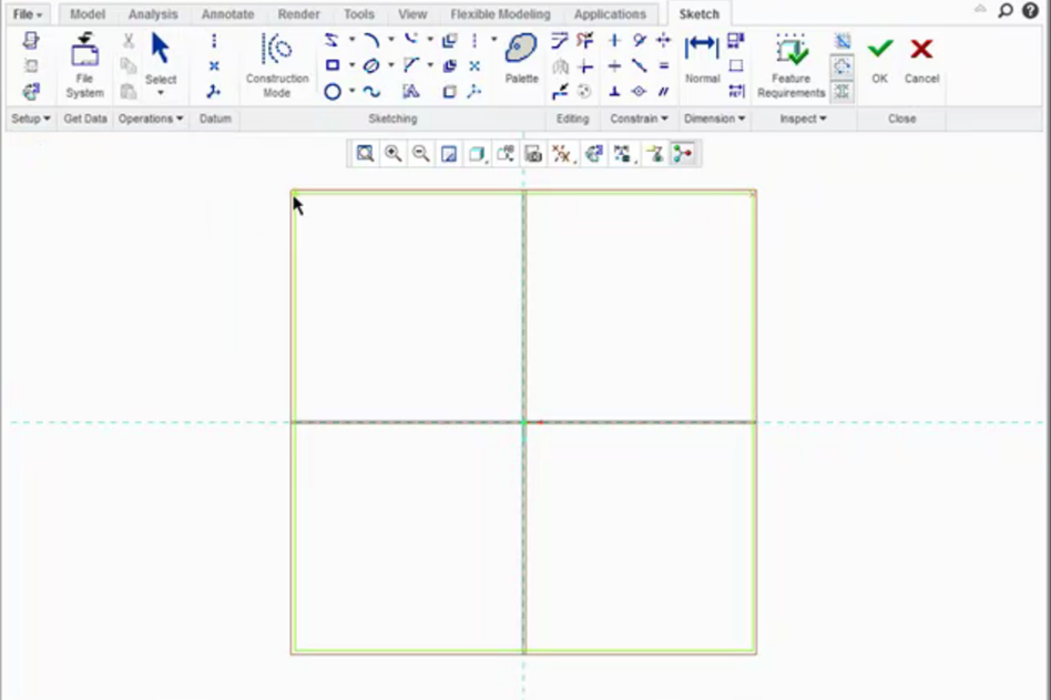
Begin by creating a square section on your first sketch plane with the Center Rectangle tool in Sketcher.

Sketch a Square Section
Step 2: Sketch a Circular Section and Divide it
Create a second sketch plane offset from the one on which you sketched your square section. Sketch a circle on this sketch plane using the same center that you used for your center rectangle.
Each section of the blend must have the same number of entities. You will tell PTC Creo how to blend the two sections together by splitting the circle into four segments to match the four segments of the square section.
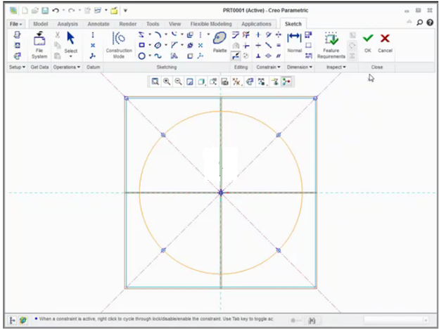
First, orient the sketching plane parallel to the screen with the Sketch View button. You will see the square section and the circular section together. Next, select the References command and select the corners of the square section as references for the sketch. Then create two centerlines diagonally across the square through the corner references, and use the Divide tool to split the circle where it is intersected by the centerlines.

Divide the square and circle into an equal number of segments. This allows you to create the blend.
Step 3: Create the blend.
Create a blend with the Blend tool. Select “Selected Sections” under the Sections panel. Select the rectangular section as Section 1, then Insert, then the circular section as Section 2. If the blend is twisted, you can adjust the start point of either section by selecting the section in the collector and then dragging the vertex around the section. Here is an example of what the blend looks like:

The final product: A square to round blend
In conclusion, creating a square to round blend in PTC Creo Parametric can be accomplished in a few easy steps.
Check out our video tutorial on the PTC University Learning Exchange (“Creating a Square to Round Blend in PTC Creo Parametric 2.0”) to see this advice in action. We’d also love to hear your suggestions for working with blends in PTC Creo Parametric.
For more in-depth product feature explanations, visit our Tech Tips area.
Have some ideas about what PTC Creo product features you’d like to learn more about? Send me a message or leave a comment below and we’ll write up the best ideas from the community. Thanks for reading, looking forward to all of your feedback!
In case you missed it, here are our recent Did You Know posts:
1) How to Create a Family Table
2) Tips and Tricks for Cable Design in PTC Creo Parametric Piping and Cabling Extension
- Mark as Read
- Mark as New
- Bookmark
- Permalink
- Notify Moderator
Thats great, exept for sheet metal it's not very useful. I would imagine that duct work or tubing is where this would be used a lot. You can't get bend lines or angles using this method. Do you have any methods for creating that? We actually had to buy a third party software to do this for us to make manufacturable models. Kind of sad when you think about how much you have to pay for this software.
- Mark as Read
- Mark as New
- Bookmark
- Permalink
- Notify Moderator
Don't forget about the tangency control where normal works well at the section plane, and tangent works well if you need to blend the feature to existing geomtery.
(someone needs to look at the forum video feed. It fails too often!)

