

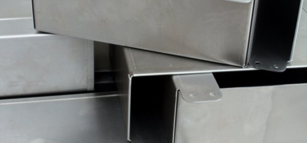
Did You Know? Edit Sheet Metal Corner Seams with Flexible Modeling
A while ago, we introduced “flexible modeling” into Creo. Flexible modeling adds direct modeling capabilities to our traditionally parametric 3D CAD system, so you can easily make changes to a model (thanks to flexible modeling) while retaining design intent (thanks to parametric modeling).
Flexible modeling is especially useful for early concept design work in which models change often, as well as for last-minute changes to existing models.
Now, with Creo 4.0, we’ve extended flexible modeling to Sheetmetal Design. In this post, our expert demonstrates how it works, showing you how to change corner seams on a sample part.
In Creo Parametric 4.0 Sheetmetal Design, you can use flexible modeling to edit the corner seams of a sheet metal part independent of how the part was created, even if it was imported from another CAD system.You can change parameters and controls in the mini toolbar or in the ribbon.
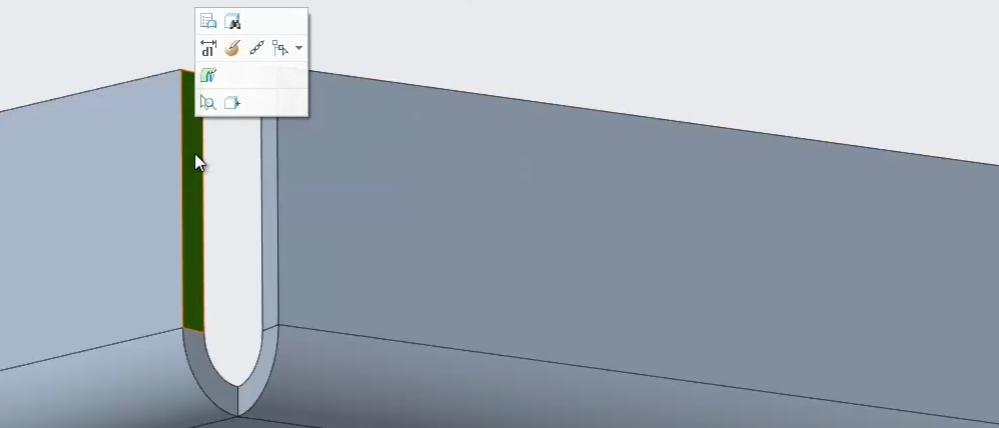
The mini toolbar opens when a corner seam is selected.
Additionally, for fast access, right-click to select what type of solution you want to use, such as Gap, Blind, or Overlap.
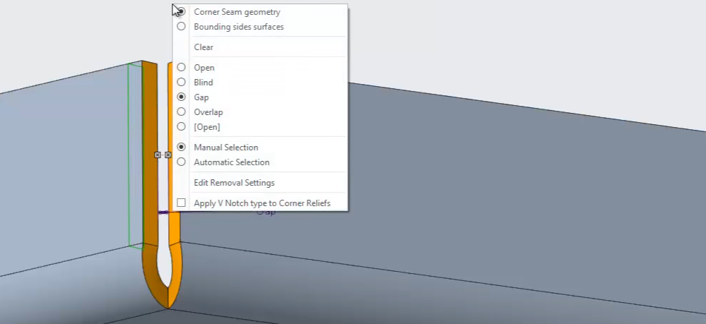
Changing the type of seam with a right-click.
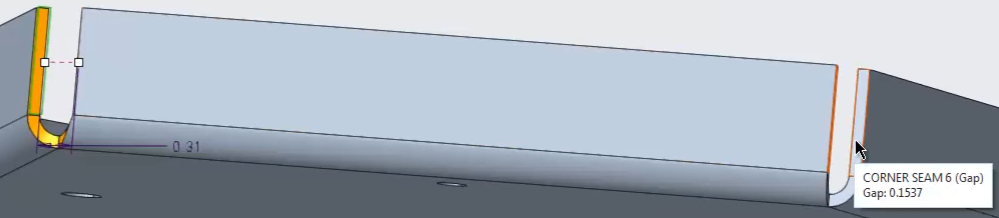
Using Overlap, you can easily switch between the preferred side by flipping the side or switching back to the Gap solution. Use the dragger to easily define dimensions for the size of the gap.
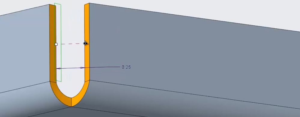
Dragging to change the size of the gap.
By selecting more surfaces of other corner seams, the definition is propagated to these recognized corner seams.
Copying a seam definition from one seam (left) to another (right).
We can also define a corner seam in situations where the system doesn’t automatically recognize a corner seam. Simply select the surface, and then click Edit Corner Seam.
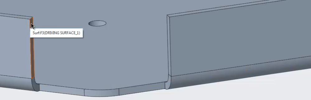
A corner where the seam wasn’t automatically detected.
The bend and wall definition are then analyzed and a possible solution for a corner seam is presented.
When creating this wall in the past, the corner seam definition for the neighbor wall was not specified. The power of the Creo 4.0 Corner Seams tool is the ability to also handle this type of situation.
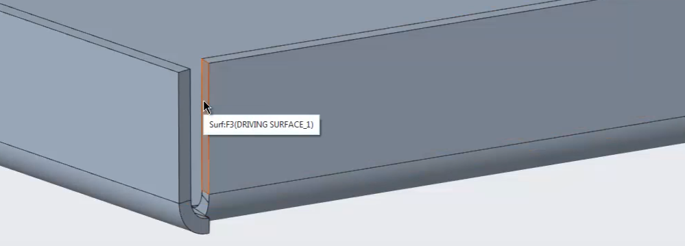
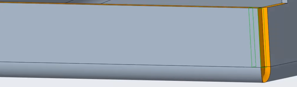
Selecting a face of the corner.
Click Edit Corner Seam, and select the surface of the corner seam. The neighbor conditions are analyzed and a possible solution is presented.
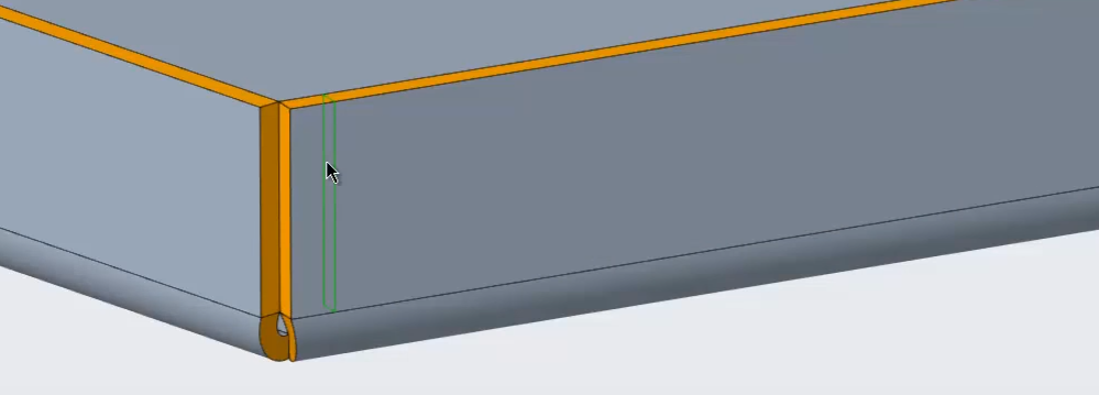
Creo analyzed the corner and suggested a proper seam.
You can then select between different options to specify the expected corner seam.
To apply the same corner seam solution at the other side of the wall, add the surface of the other corner seam—or just select the bend surface, and the same options and parameters are applied to the other side of the wall. Note that the part is an imported model.
The same seam applied to the other end of the wall.
Edit Corner Seam gives you the power to change or define corner seams in a sheet metal part in complex situations. Again, you can make these changes independent of how the part was created, even if it was imported from another CAD system.
To see a demo of these features, check out the video:
You can also learn more by reading the PTC Creo Help Center page, New Edit Corner Seam Tool.
If you haven’t already, download the software here and try it yourself. And stay tuned to our “Did You Know” blog series, as we cover more enhancements in PTC Creo 4.0.