- Community
- Model Based Enterprise
- Discussions
- Re: Is it possible to create geometric tolerance r...
- Subscribe to RSS Feed
- Mark Topic as New
- Mark Topic as Read
- Float this Topic for Current User
- Bookmark
- Subscribe
- Mute
- Printer Friendly Page
Is it possible to create geometric tolerance related to a splitted datum feature?
- Mark as New
- Bookmark
- Subscribe
- Mute
- Subscribe to RSS Feed
- Permalink
- Notify Moderator
Is it possible to create geometric tolerance related to a splitted datum feature?
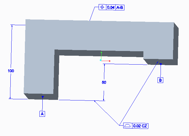
Is it possible to create geometric tolerance related to a spitted datum feature that was build out of two surfaces 2xA or A & B?
The tolerance zone should be created as common zone (CZ behind the tolerance value)

- Tags:
- group discussion
- Mark as New
- Bookmark
- Subscribe
- Mute
- Subscribe to RSS Feed
- Permalink
- Notify Moderator
If you add the geometric tolerance to one surface, you can then select the geometric tolerance box, right click and edit the attachment to add another leader in the drawing. With regards to the CZ, this is done by adding additional text as a suffix with a space then CZ
HTH
- Mark as New
- Bookmark
- Subscribe
- Mute
- Subscribe to RSS Feed
- Permalink
- Notify Moderator
In addition to Terry's correct response, I'd like to add some help for people that would like to do vertical common zones:
1. select "Normal Leader" for your first attachment when editing the properties of your geometric tolerance.
2. select "Attachment" in the Annotate tab. Add a reference, and follow the instructions in the message log. The second attachment will automatically be attached the same way with multiple other lines to manipulate.
3. to reorient the geometric tolerance, select it then select "Text Style" and edit the angle to 90 or 270 degrees.
4. right-click the geometric tolerance then toggle the leader type so that it is not directly attached to its own witness line.
5. Adjust things to look nice.
I hope that helps some people as it took me almost forever to figure out and is still difficult to manipulate.
- Mark as New
- Bookmark
- Subscribe
- Mute
- Subscribe to RSS Feed
- Permalink
- Notify Moderator
Also in addition to Terry's and Christoph response, it works.
But i am not able to "add leader" to the second dimension line, the "add leader" wants to have a surface or a geometry from the model, i can't catch the second dimension line ![]()
Also a call from myside....i am not able to "insert jog" in 3D (this is only available in 2D)


