
Turn on suggestions
Auto-suggest helps you quickly narrow down your search results by suggesting possible matches as you type.
Showing results for
Please log in to access translation
Turn on suggestions
Auto-suggest helps you quickly narrow down your search results by suggesting possible matches as you type.
Showing results for
Community Tip - You can Bookmark boards, posts or articles that you'd like to access again easily! X
- Community
- Creo Elements Direct
- Drafting
- Re: cylindrical csys enforced displacement constra...
Translate the entire conversation x
Please log in to access translation
Options
- Subscribe to RSS Feed
- Mark Topic as New
- Mark Topic as Read
- Float this Topic for Current User
- Bookmark
- Subscribe
- Mute
- Printer Friendly Page
cylindrical csys enforced displacement constraints
May 14, 2014
12:00 PM
- Mark as New
- Bookmark
- Subscribe
- Mute
- Subscribe to RSS Feed
- Permalink
- Notify Moderator
Please log in to access translation
May 14, 2014
12:00 PM
cylindrical csys enforced displacement constraints
Hello All,
A simple model comprising a cylindrical bar held at one end.
The constraint is defined in a cylindrical csys as it is desired the bar should rotate relative to an applied load.
The rotation should be achieved using an enforced displacement constraint.
The enforced displacement is THETA.
I would have expected the bar to rotate, (rigid body) but instead the elements on the constrained face wind up.
Model attached. (which can't get much simpler) No forces applied. Only one enforced displacement constraint. everything linear.
small mpg attached for those who don't want to run a model.
Can someone point out the obvious mistake.
Thanks
This thread is inactive and closed by the PTC Community Management Team. If you would like to provide a reply and re-open this thread, please notify the moderator and reference the thread. You may also use "Start a topic" button to ask a new question. Please be sure to include what version of the PTC product you are using so another community member knowledgeable about your version may be able to assist.
Solved! Go to Solution.
Labels:
- Labels:
-
General
ACCEPTED SOLUTION
Accepted Solutions
May 15, 2014
10:43 AM
- Mark as New
- Bookmark
- Subscribe
- Mute
- Subscribe to RSS Feed
- Permalink
- Notify Moderator
Please log in to access translation
May 15, 2014
10:43 AM
Hi Guys!
Nice one:
I've been running your example several times, there is one typical oops in your reasoning:
You've prescribed a tengential displacement of 10 mm to an entire face, that is not friendly....
The inner diameter would have to rotate more than the outer diameter. Hence the stress.
A prescibed angle in radians should solve this
However, this is not the only issue.
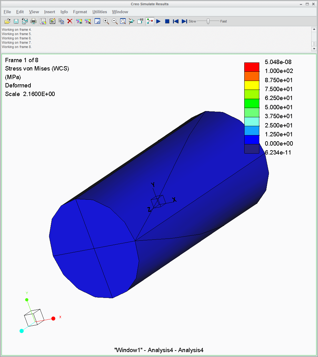
I've made some neat constraints, on the edges in stead of the surface. I see nice rotation (in linear analysis, with a scale factor applied this looks like the shaft is blowing up, but this is due to the scale factor).
It's still not perfect, I do get some stresses (picture 1)
You do have no stiffness, which should make this a singular analysis somewhere. This may cause the effect.
5 REPLIES 5
May 14, 2014
12:06 PM
- Mark as New
- Bookmark
- Subscribe
- Mute
- Subscribe to RSS Feed
- Permalink
- Notify Moderator
Please log in to access translation
May 14, 2014
12:06 PM
Just thinking out loud: What are the units (dimensions) of theta displacement? Is it angular, or (pseudo-)linear?
Have you used Total Load At Point? If so, try not using it... if not, try using it!
May 14, 2014
12:31 PM
- Mark as New
- Bookmark
- Subscribe
- Mute
- Subscribe to RSS Feed
- Permalink
- Notify Moderator
Please log in to access translation
May 14, 2014
12:31 PM
Hi Jonathan,
There are no loads at all, only the enforced displacement constraint
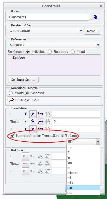
The constraint is defined in the cylindrical csys whose axis is on the axis of the bar. The Theta of the constraint enforced (Z&R are fixed).
The units of the theta are degrees. (the 'interpret angular translations as radians' check box in the constraint dialogue is UN checked).
I put 10 degrees in (very visible movement).
I thought it may have something to do with the requested large displacement so I switched on large deformations. The simple model fails complaining about high compressive strain so I assume the same thing is happening.
Forgot to mention,
Creo2.0 M100
I haven't tried other s/w cuts/versions yet
Regards
Charles
May 14, 2014
12:34 PM
- Mark as New
- Bookmark
- Subscribe
- Mute
- Subscribe to RSS Feed
- Permalink
- Notify Moderator
Please log in to access translation
May 14, 2014
12:34 PM
Of course... TLAP only applies to loads, not constraints.
Duh, stupid me!
May 15, 2014
10:43 AM
- Mark as New
- Bookmark
- Subscribe
- Mute
- Subscribe to RSS Feed
- Permalink
- Notify Moderator
Please log in to access translation
May 15, 2014
10:43 AM
Hi Guys!
Nice one:
I've been running your example several times, there is one typical oops in your reasoning:
You've prescribed a tengential displacement of 10 mm to an entire face, that is not friendly....
The inner diameter would have to rotate more than the outer diameter. Hence the stress.
A prescibed angle in radians should solve this
However, this is not the only issue.
I've made some neat constraints, on the edges in stead of the surface. I see nice rotation (in linear analysis, with a scale factor applied this looks like the shaft is blowing up, but this is due to the scale factor).
It's still not perfect, I do get some stresses (picture 1)
You do have no stiffness, which should make this a singular analysis somewhere. This may cause the effect.
May 15, 2014
11:19 AM
- Mark as New
- Bookmark
- Subscribe
- Mute
- Subscribe to RSS Feed
- Permalink
- Notify Moderator
Please log in to access translation
May 15, 2014
11:19 AM
Erik, that's great.
I just tried it with the 'interpret angular translations as radians' check box in the constraint dialogue is CHECKED and put in 0.2 radians. (not sure why I didn't try that yesterday)
I misinterpretted the check box and drop down.
In my mind, a translation in theta must be an angle. I assumed the linear dimension dropdown was wrong (clearly it isn't)
I then further concluded that the check box enables the user to decide whether values should be degrees or radians.
So folks, it's moving all points of the surface 10mm in the theta direction (which must be undefined at the centre) unless you use the check box. pic and movie attached.
Regards
Charles
Announcements


Top Tags
