Community Tip - Visit the PTCooler (the community lounge) to get to know your fellow community members and check out some of Dale's Friday Humor posts! X
- Community
- Creo Elements Direct
- Modeling
- Re: Loading a lisp by toolbar button
- Subscribe to RSS Feed
- Mark Topic as New
- Mark Topic as Read
- Float this Topic for Current User
- Bookmark
- Subscribe
- Mute
- Printer Friendly Page
Loading a lisp by toolbar button
- Mark as New
- Bookmark
- Subscribe
- Mute
- Subscribe to RSS Feed
- Permalink
- Notify Moderator
Loading a lisp by toolbar button
Hello,
I have a .lisp file that I have to continually drag and drop into Creo Elements Direct 18.10 for it to work. Is it possible to have it located in a folder and create a toolbar button that will go out and load it instead of having to drag and drop it?
Thanks for any help in advance!
- Labels:
-
General
- Mark as New
- Bookmark
- Subscribe
- Mute
- Subscribe to RSS Feed
- Permalink
- Notify Moderator
Hi
Usually, all your own Lisp files are stored in a specific folder from which they are loaded.
For example, let's take this path:
C:\User\Lisp\...
And as an example, let's take this program:
example_1.lsp
Then it is loaded with this string:
(load "C:/User/Lisp/Example_1.lsp")
Attention, the slash must be "/" and always in brackets
Now there are different ways to load this:
1. Direct entry into the command line:
2. Load when the program is started.
To do this, the above string must be written into a start file.
This is the sd_customize (for 3D) or the am_customize (for annotation).
They can be found in the User Customization Directory.
(File - Settings - UI ... - Customizations - Show Directory)
If it does not exist, simply create an empty text file without an extension.
Example of the location of the setup files:
C:\Users\USERNAME\AppData\Roaming\PTC\Creo Elements DirectModeling xxx\xxx\ .. (the am_customize in folder ANNOTATION)
( ! This could look completely different in a company network ! ).
After loading, the little helpers can be found in the toolbox ![]()
If you still want a toolbar button, ask again.
- Mark as New
- Bookmark
- Subscribe
- Mute
- Subscribe to RSS Feed
- Permalink
- Notify Moderator
Thanks FriedhelmK,
Thank you very much for the detailed explanation of how to load a lisp thru the command line. I am working thru a company network and believe I am locked out of editing that setup file. I created a Toolbar button by writing a macro that loads thru the command line and then opens up the toolbox and grabs it. is there another way of creating a toolbar button that skips the macro step?
Also while I have your attention, do you know of a way to Upload a .TXT file to create a spline? Seems the only answers I get from people in regards to that question is someone using Parametric so its nice to talk with another Elements/Direct user.
- Mark as New
- Bookmark
- Subscribe
- Mute
- Subscribe to RSS Feed
- Permalink
- Notify Moderator
A simple way to do that is to make some simple changes to the .TXT file so that when it is loaded it will create the spline. Here's an example:
CREATE_BSPLINE
:wire_part "/Spline"
20.000,00.000,00.000
00.000,00.000,-20.000
-20.000,10.000,00.000
00.000,20.000,30.000
30.000,30.000,00.000
00.000,30.000,-20.000
-20.000,30.000,00.000
00.000,30.000,30.000
30.000,10.000,00.000
complete
In that example, you just add the command to create a spline, then specify what part you want the spline added to, include each point of the spline on a separate line (X, Y, Z), and then specify that you are done with "complete".
It is possible to write a command which automates that so you don't have to modify the text file, and even generate a part name if you want. That takes some programming work, so unless you will be doing this a lot, the simple approach to just modifying the text file may be adequate for you.
- Mark as New
- Bookmark
- Subscribe
- Mute
- Subscribe to RSS Feed
- Permalink
- Notify Moderator
hi k
>I am locked out of editing that setup file
dit you try it ? The sd_customize in
C:\Users\USERNAME\AppData\Roaming\PTC\Creo Elements DirectModeling xxx\xxx\ ..
is on your local disc.
You can load the lisp. OK
Once loaded, the lisp remains for the session in memory.
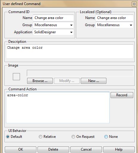
After that, you only need a button that starts the lisp.
Edit the file;lsp and copy the string behind
(Sd-defdialog '
Exemple:
(In-package: custom)
(Use-package: oli)
;; -------------------------------
(Sd-defdialog 'area-color
: Dialog-title "Change area color"
: Toolbox-button t
: Variables


