Turn on suggestions
Auto-suggest helps you quickly narrow down your search results by suggesting possible matches as you type.
Showing results for
Turn on suggestions
Auto-suggest helps you quickly narrow down your search results by suggesting possible matches as you type.
Showing results for
- Community
- Creo+ and Creo Parametric
- 3D Part & Assembly Design
- Create hex/pentagon shaped dimples on a circular s...
Options
- Subscribe to RSS Feed
- Mark Topic as New
- Mark Topic as Read
- Float this Topic for Current User
- Bookmark
- Subscribe
- Mute
- Printer Friendly Page
Create hex/pentagon shaped dimples on a circular surface.
Jun 07, 2013
10:02 PM
- Mark as New
- Bookmark
- Subscribe
- Mute
- Subscribe to RSS Feed
- Permalink
- Notify Moderator
Jun 07, 2013
10:02 PM
Create hex/pentagon shaped dimples on a circular surface.
Okay, I know we just had a huge long discussion on round dimples on a circular surface while keeping the round dimple profile. This truly is for a purpose, I'm not just trying to waste time. It is the same concept but instead of a circular dimple I'm trying to create a hex or pentagon shaped dimple. If you are familiar with golfing, look at a callaway golf ball dimple pattern, it is a pentagon. It is that same concept but as opposed to a spherical shape I'm trying to put that on a circular shape just like my last discussion.
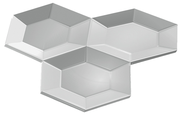
Example of the callaway golf ball dimple and an image I found that might be helpful. I've been playing with this for a while and can't figure out how to do it. The bottom of the dimple doesn't have to be perfectly spherical, in fact that's impossible. I do want it to be or appear as smooth or spherical as possible however.

Thank you!
Labels:
- Labels:
-
General
21 REPLIES 21
Jun 07, 2013
11:15 PM
- Mark as New
- Bookmark
- Subscribe
- Mute
- Subscribe to RSS Feed
- Permalink
- Notify Moderator
Jun 07, 2013
11:15 PM
Same as the circular dimples (use a VSS) but use a conic instead of a arc. If you feel really experimental (or some kind of mental...) add a trajpar to the sharpness value. Just remember that the VSS origin curve or chain curve must be tangent throughout.
As for making the hex correct on the cylinder, take a look at the wrap feature. That will keep you busy too 
Jun 08, 2013
12:35 AM
- Mark as New
- Bookmark
- Subscribe
- Mute
- Subscribe to RSS Feed
- Permalink
- Notify Moderator
Jun 08, 2013
12:35 AM
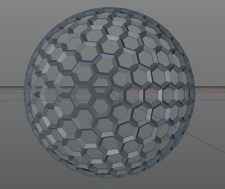
Something like this?
Jun 08, 2013
02:54 AM
- Mark as New
- Bookmark
- Subscribe
- Mute
- Subscribe to RSS Feed
- Permalink
- Notify Moderator
Jun 08, 2013
02:54 AM
"How to give your CPU a heart attack!"
there's got to be a texture opportunity with that one.
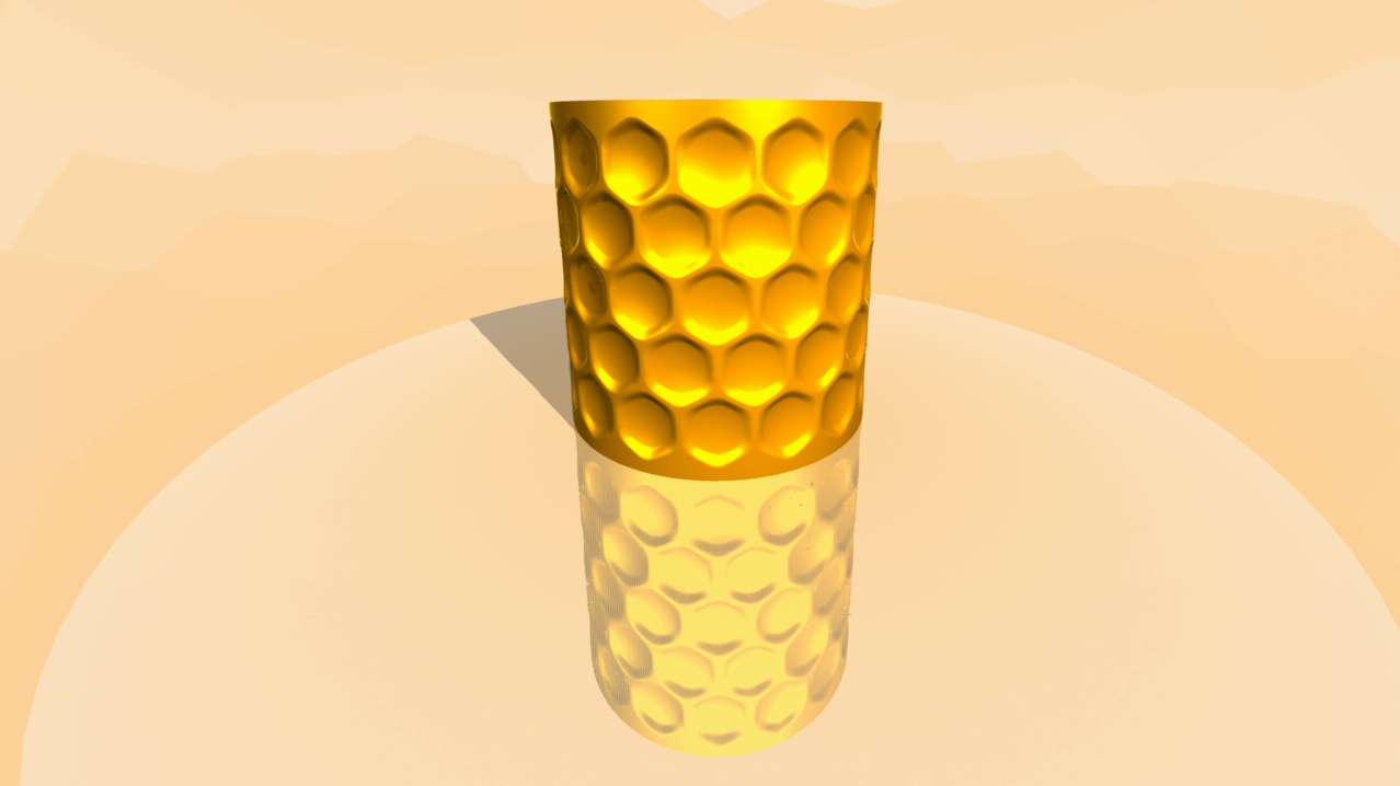
Doing this one made it clear that mapping the hex with the wrap feature is required. This makes it possible to use the Fill Pattern and have a common "frame" width around each instance on all 6 sides.
VSS; simple section with arc and spline using 3 guide strings. No rounds!
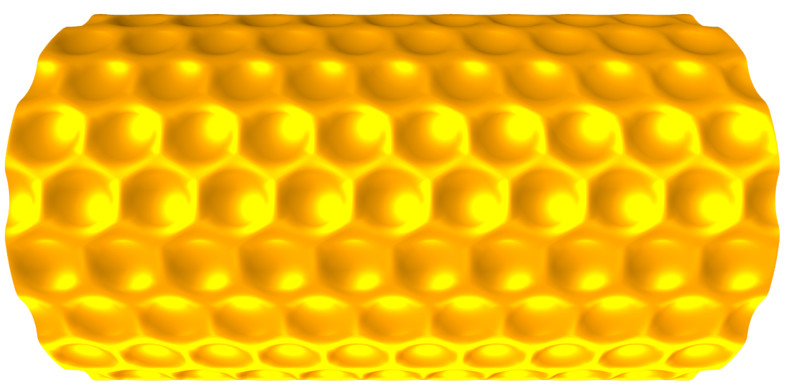

Can't you just see the honey drip'n from these 
Okay, the tech...
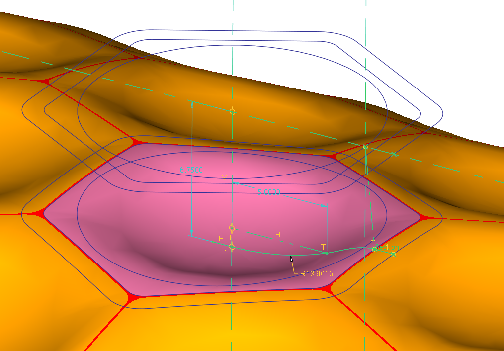
And yes, you can use the trick from the dimple discussion to merge the fill pattern all-around matching up perfectly. In this case, I sized the cylinder to the pattern: 15mm hex across the flats; patterned at 15.1; cylinder height 151 (10 and 9+2x1/2); and 12 around (24-offset).
Jun 08, 2013
05:52 AM
- Mark as New
- Bookmark
- Subscribe
- Mute
- Subscribe to RSS Feed
- Permalink
- Notify Moderator
Jun 08, 2013
05:52 AM
I can even smell the honey. 
Feb 22, 2017
07:17 AM
- Mark as New
- Bookmark
- Subscribe
- Mute
- Subscribe to RSS Feed
- Permalink
- Notify Moderator
Feb 22, 2017
07:17 AM
can you please make a video of modeling on the below-attached image.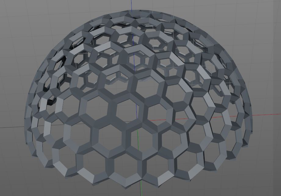
Jun 08, 2013
10:41 AM
- Mark as New
- Bookmark
- Subscribe
- Mute
- Subscribe to RSS Feed
- Permalink
- Notify Moderator
Jun 08, 2013
10:41 AM
What do you mean for making it correct on the cylinder, isn't that the purpose of the extrude and intersect features?
I've got a lot to learn in Pro E, I can't get my cross section in the VSS to work for me.
Jun 08, 2013
12:48 PM
- Mark as New
- Bookmark
- Subscribe
- Mute
- Subscribe to RSS Feed
- Permalink
- Notify Moderator
Jun 08, 2013
12:48 PM
Actually no. When we did the circle, "we" wanted it to be visually circular from a dead on view. I also wanted to keep it simple since the pattern was rather loose.
Since we are continuing the discussion, I went for introducing mapping accuracy. On cylinders, there is a "slight" difference but a key difference you will use more often that you expect.
With the circle projection method, you will find that the width of the actual arc diameter along the cylinder (arclength) is longer than the height along the cylinder's axis. This means that if you went for a very tight pattern, like the hex pattern, you would have found different gaps vertically and horizontally or you would be adjusting the pattern to match it, if you even could (fill patterns are not fully controllable).
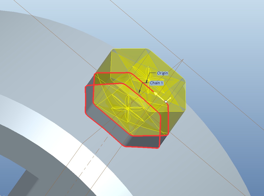
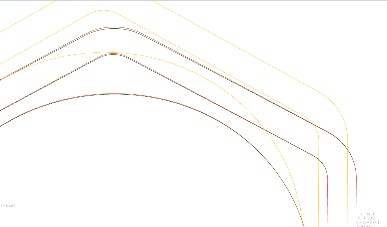
Here are the two methods overlayed:
- Yellow is the original planar sketch
- Red is the Projected sketch
- Green is the Wrapped sketch
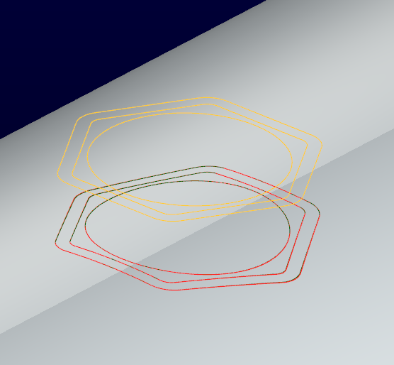
A closeup will reveal the difference.
The smaller the cylinder or the larger the feature, the more pronounced this becomes. When you need absolute accuracy to manage features on a cylinder, wrapping becomes a very powerful tool. In the case shown here, matching the fill pattern all the way around required absolute accuracy of the sketch I used to define the diameter of the cylinder (remember, I opted for a fixed feature size this time). That slight difference would have to have been accounted for since the error would have been multiplied by 24 (12 and 12).
One tip for wrapping; insert a coordinate system in your sketch (it doesn't need to be the datum CSYS). This makes wrapping much more accurate when placing it. Otherwise, your entire sketch could be offset based on a bounding box Creo is using to place the wrapped sketch. You have to trust me on this one. Use a sketch CSYS in all your Wraps!
Jun 08, 2013
01:52 PM
- Mark as New
- Bookmark
- Subscribe
- Mute
- Subscribe to RSS Feed
- Permalink
- Notify Moderator
Jun 08, 2013
01:52 PM
Could you attach an example part so I can see exactly what you did?
Jun 08, 2013
02:00 PM
- Mark as New
- Bookmark
- Subscribe
- Mute
- Subscribe to RSS Feed
- Permalink
- Notify Moderator
Jun 08, 2013
02:00 PM
Sure. This is the 1st one I did. it will give you the idea for creating Wrap features. It is not yet optimized for patterning.
Jun 08, 2013
02:11 PM
- Mark as New
- Bookmark
- Subscribe
- Mute
- Subscribe to RSS Feed
- Permalink
- Notify Moderator
Jun 08, 2013
02:11 PM
What version of Pro E are you on?
Jun 08, 2013
02:23 PM
- Mark as New
- Bookmark
- Subscribe
- Mute
- Subscribe to RSS Feed
- Permalink
- Notify Moderator
Jun 08, 2013
02:23 PM
yea... Creo 2.0 full version.
Are you stuck on a particular command?
You're on WF right?
Jun 08, 2013
03:05 PM
- Mark as New
- Bookmark
- Subscribe
- Mute
- Subscribe to RSS Feed
- Permalink
- Notify Moderator
Jun 08, 2013
03:05 PM
I'm on Creo Pro 5 but I do have WF 4 as well. What I've done is this:
1. Extruded Hexagon with full tangent chain.
2. Intersect with circular surface
3. Create VSS...(This is where it keeps breaking on me. I cannot figure out how to use the conic feature. Or better said I cannot figure out how to create the section for the VSS)
4. As far as the wrap and patterns that you have done above I have very little to no experience using the wrap tool. Thats why I thought it would be good to see an example part to step through it and see how you did it. Sure wish they made .prt files backwards compatible.
Jun 08, 2013
03:50 PM
- Mark as New
- Bookmark
- Subscribe
- Mute
- Subscribe to RSS Feed
- Permalink
- Notify Moderator
Jun 08, 2013
03:50 PM
Well, they do make them backwards compatible if you want to use the conversion tool Granite. You'll have to do some research on how to use it.
You do want to learn to use wrap if you are going to be working with cylindrical objects. It is fairly basic. Normally you use relations to manage positions on the cylinder. Wrap also works on different surface shapes, but cylinders are what I have used mostly thus far.
The secret to the VSS I used is that the origin curve is a circle. This makes sure that the profile sketch points to the center throughout the sweep. The chain curves make sure the variable sketch follows the intended pattern.
In every VSS sweep where you have more than the origin curve, you get "references" in the sketch for the additional guide curves. These are critical in making VSS work for you. If you over-constrain the sketch, it will remove the "variable" part of the sweep (not that it warns you about this). If you have an origin curve and a chain curve (2 guides), draw a line between the two points provided when you create the sketch. Nothing else, just lock the two ends on the provided references. And the line will follow the curves on both ends as long as they are the same length (closed loops are always the "same length: 0 to 1 ").
The VSS profile sketches are very touchy. It takes very little for one to fail. You might have a perfectly working section and a little tweak fails it. Just know if you don't get a preview, or if the preview does not vary, something is wrong in the sketch. The sketch -must- work throughout the sweep.
Again, in the early example you show, you are sweeping along the hex as an origin curve. I can see that by the flower pedals it created. If the origin sketch is a circle, this won't happened. The chain, the second curve guide will do the variation along the surface.
The 2nd guide curve you see in my wrap feature is to manage tangency to some extent. It is not perfect because of the curved surface, but it serves to change the angle of the spline in the sketch so it provides a pseudo tangency. Of course, if you need perfect tangency, use the round feature after creating the dimple with an edge. This would be a perfect place for a continuous curvature round but be aware that you get less control over the tangent edges. It is all a trade-off.
We have a lot of discussion on the VSS here on the forum. Please do a search and wade through the garden of knowledge. It is worth every minute to understand this feature.
Use the wrap feature if you want a tight pattern. You'll thank yourself later.
BTW: Can you share the project you're working on?
Jun 08, 2013
09:48 PM
- Mark as New
- Bookmark
- Subscribe
- Mute
- Subscribe to RSS Feed
- Permalink
- Notify Moderator
Jun 08, 2013
09:48 PM
Here is a quick video on mapping sketches using wrap vs project.
Jun 10, 2013
08:01 AM
- Mark as New
- Bookmark
- Subscribe
- Mute
- Subscribe to RSS Feed
- Permalink
- Notify Moderator
Jun 10, 2013
08:01 AM
All very helpful, thank you for the video. I tried to download granite but the link on PTC website for the version I need is broken, hopefully that gets resolved soon. At this point in the project I cannot share what I'm working on. I hope to be able to eventually. Thank you again for all your help!
Jun 10, 2013
08:08 AM
- Mark as New
- Bookmark
- Subscribe
- Mute
- Subscribe to RSS Feed
- Permalink
- Notify Moderator
Jun 10, 2013
08:08 AM
Happy to help
Jun 14, 2013
03:27 PM
- Mark as New
- Bookmark
- Subscribe
- Mute
- Subscribe to RSS Feed
- Permalink
- Notify Moderator
Jun 14, 2013
03:27 PM
Just sent you a private message asking how to do this. I looked forever and couldn't find the bloody advanced editor button somehow. Here is my file, if you have a minute take a look at it and see if you can't figure out what I'm doing wrong. If I want my pattern to take up the entire surface of the ring even if that means incomplete hex sweeps on the edges, is that possible or does it have to be a complete sweep?
Jun 14, 2013
04:07 PM
- Mark as New
- Bookmark
- Subscribe
- Mute
- Subscribe to RSS Feed
- Permalink
- Notify Moderator
Jun 14, 2013
04:07 PM
Interesting... and very strange.
Move the pattern origin to the wrapped hex instead of the center line sketch.
That one change corrected the error.
Jun 14, 2013
04:13 PM
- Mark as New
- Bookmark
- Subscribe
- Mute
- Subscribe to RSS Feed
- Permalink
- Notify Moderator
Jun 14, 2013
04:13 PM
Sketch4 is poorly defined and doesn't allow for patterning. I removed the vertical and horizontal references for the sketch and replaced them with the axis and the outside surface. The line could be defined as horizontal and constrained coincident to the center reference and the circular edge.
I also moved Sketch4 above the sweep. Edited the pattern to again use Sketch4 as an alternate origin and it worked fine.
Jun 14, 2013
04:38 PM
- Mark as New
- Bookmark
- Subscribe
- Mute
- Subscribe to RSS Feed
- Permalink
- Notify Moderator
Jun 14, 2013
04:38 PM
Got it, I guess it was over constrained so it was messing up the pattern. Thanks for all of your help on this project. Its been a good learning experience.
Jun 15, 2013
01:30 AM
- Mark as New
- Bookmark
- Subscribe
- Mute
- Subscribe to RSS Feed
- Permalink
- Notify Moderator
Jun 15, 2013
01:30 AM
Patterns often choke on datum plane constrained features.
I will say that you might want to learn constraining a sketch fully.
In the world of PTC, neatness counts
By the way, to increase the tangent accuracy of the spline, reduce the offset of the outside wrapped hex to something very small. This tangency is an approximation after all.