
sheet metal mitered corner
- Mark as New
- Bookmark
- Subscribe
- Mute
- Subscribe to RSS Feed
- Permalink
- Notify Moderator
sheet metal mitered corner
Hi All,
I know I'm missing something. What is the best way to get these flages to be a nice meeting (say a 0.010" gap) mitered corner?
I've adde a flat, trapezoid to one flange, then the same to the other. But I'm left with a gap I cannot really modify. Can't extend any edges (the 'extend' command is usually always greyed out..)
I've startted the part as a solid, then conversion to S/M, then shelled, then added the bends & rips as required. I'm tryign to add these extra flanges (flats). Should I have created this feature in the solid before the conversion? (making an indent in the face of the solid, then adding the rip lines when converting, to get my mitered corner?)
Should I make regular rectangular flats , then unbend, then remove the corners, then do a bend back?
I guess I'm expecting something rather easy, some hidden 'miter corner flange command!
This thread is inactive and closed by the PTC Community Management Team. If you would like to provide a reply and re-open this thread, please notify the moderator and reference the thread. You may also use "Start a topic" button to ask a new question. Please be sure to include what version of the PTC product you are using so another community member knowledgeable about your version may be able to assist.
- Labels:
-
Sheet Metal Design
- Mark as New
- Bookmark
- Subscribe
- Mute
- Subscribe to RSS Feed
- Permalink
- Notify Moderator
For this part I would use "double shell" method. First shell is made in solid part, second shell is for conversion to sheet metal. First shell thickness defines flange size. Conversion feature is used for edge rips and rip connects.
When creating flat wall you have at corner of the bend line a white box which can be used for extending and shortening.
Extend feature is a bit strange, to use it you must first change selection filter (on the lower right corner of main window) from Smart to Geometry. Then you select the edge you want to extend and the feature is available.
- Mark as New
- Bookmark
- Subscribe
- Mute
- Subscribe to RSS Feed
- Permalink
- Notify Moderator
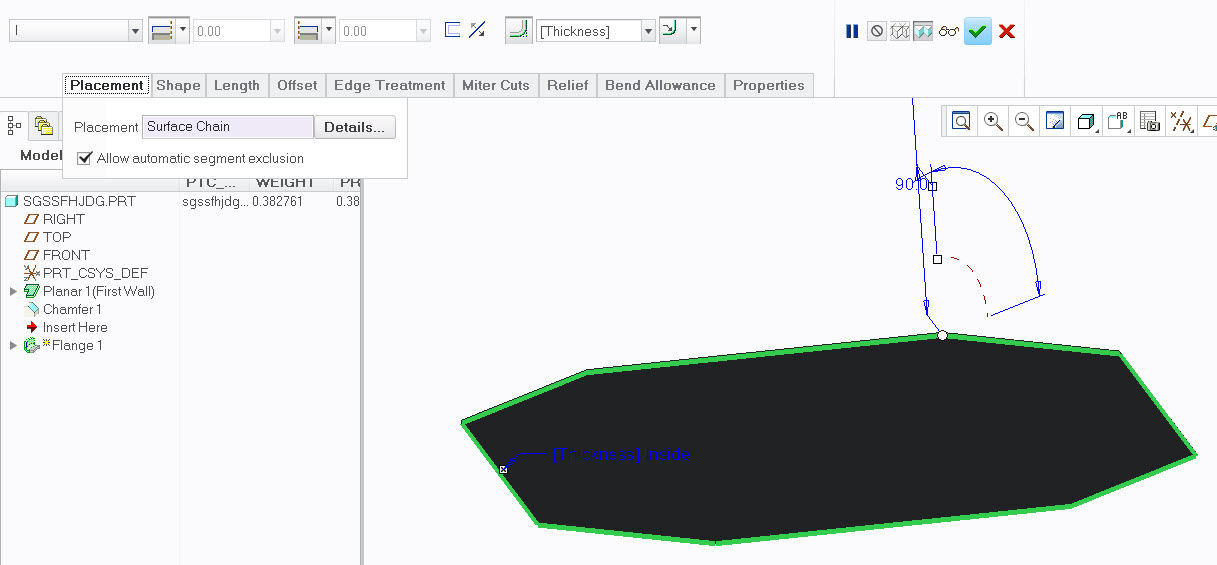
I prefer using the Flange Wall feature in Sheetmetal as this can be used with a Surface Loop.
Create a Planar bottom. Select one edge then while pressing Shift key click on bottom surface to select Surface Loop.
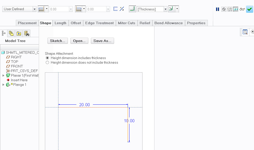
In Flange command select User Defined from drop down list and Sketch as below.
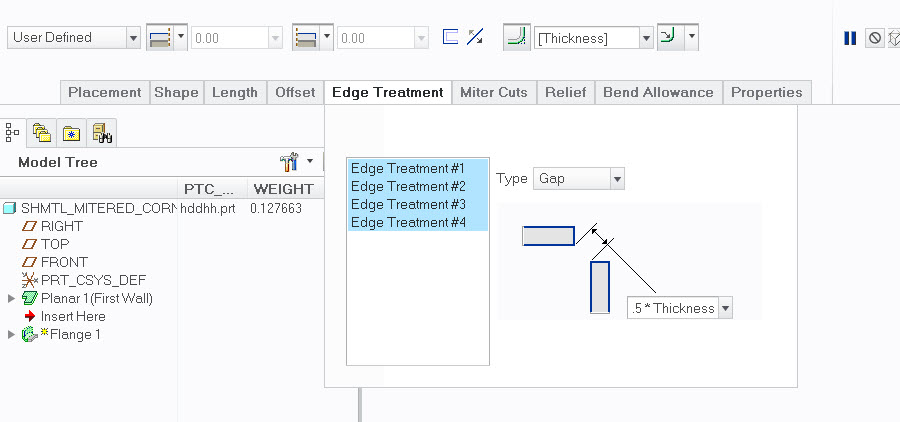
You gan adjust edge corner gap as in pic under Edge Treatment. Select all edges using Shift key before changing. If you select Blind there will be no gap.
- Mark as New
- Bookmark
- Subscribe
- Mute
- Subscribe to RSS Feed
- Permalink
- Notify Moderator
Thanks Magnus,
Am just tryign this, but I've noticed that Creo craps out when the angles aren't 90°. In my particular case, this methods works until the 3rd edge. it's not 90° to its neighbor, more like 150°.. It looks like the bend radii run into each other & don't play nice..
So, back to solid, shell, conversion, and then add my flanges & miters by hand.. that works. this, no.
- Mark as New
- Bookmark
- Subscribe
- Mute
- Subscribe to RSS Feed
- Permalink
- Notify Moderator
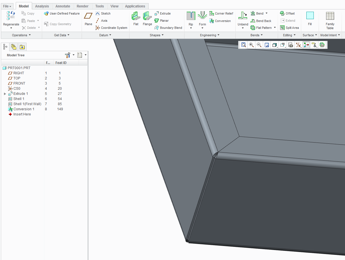
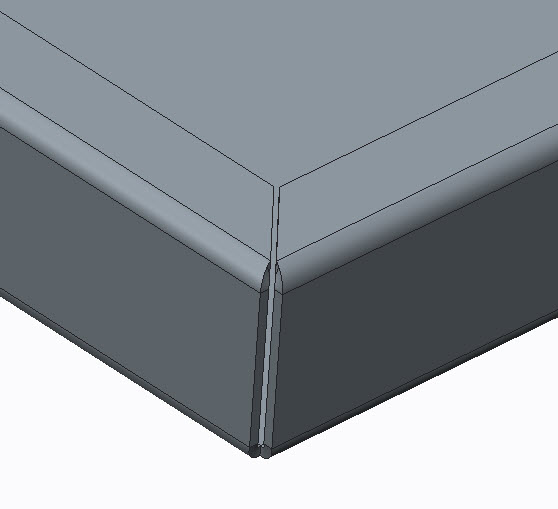
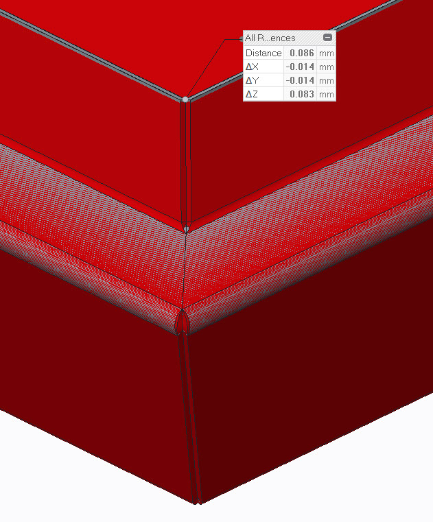
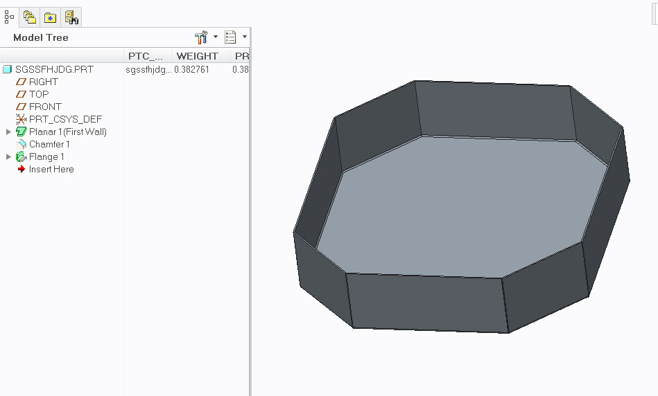
Not sure what you mean with "craps out". To me it seems that the differences are pretty minor but it just might be my view. Here's a comparison between the two options. Grey model is Shell Conversion and Red model is Flange Wall.
- Mark as New
- Bookmark
- Subscribe
- Mute
- Subscribe to RSS Feed
- Permalink
- Notify Moderator
Hi Magnus,
Try a corner that's not 90°. Try a corner that's greater 120°
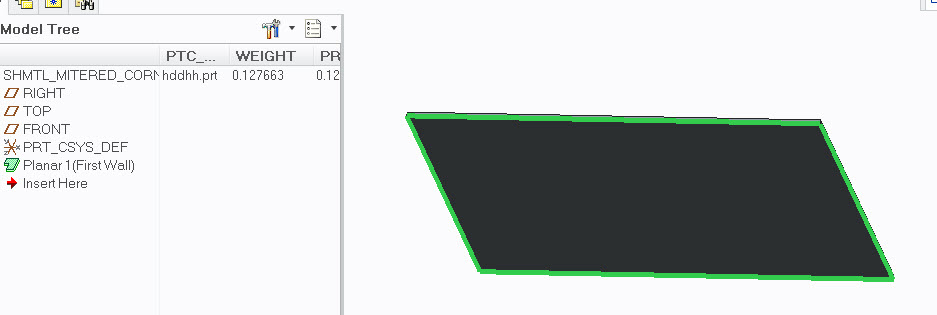
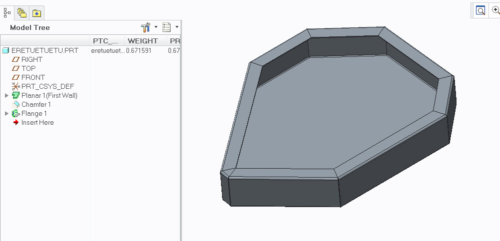
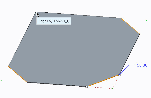
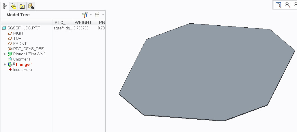
Try this, as it's close to waht I'm trying to get. make a 5 sided planar flat to start. it's about 36" X 40" with a the short part at about 4". See Picture.. Then try the sweep flange. The littel short section near that ~150° corner is where it fails. I can do it from a solid, but not a swept flange. As I've mentioned, anything over 90°, Creo seems to crap out / dosen't know what to do / can't figure out how to lay a bend radius..

- Mark as New
- Bookmark
- Subscribe
- Mute
- Subscribe to RSS Feed
- Permalink
- Notify Moderator
Hi Paul,
Ok, now I see what you're trying to do. I wasn't aware that the Flange Wall had these odd limitations. It's not the angle itself but a sort of symmetrical shape is necessary. A hexagon is possible and you can twist it a lot as in attached pic but if I have one straighter corner it won't work. Very odd.
Would be interesting to hear a reply from tech support....but my guess is that it would be 'intended functionality'.
- Mark as New
- Bookmark
- Subscribe
- Mute
- Subscribe to RSS Feed
- Permalink
- Notify Moderator
Thanks Magnus,
I know it's not me then!! (Nice to know!). Thank you for your help & confirmation. Now, to contact tech support!
- Mark as New
- Bookmark
- Subscribe
- Mute
- Subscribe to RSS Feed
- Permalink
- Notify Moderator
I think I fixed it. It's an accuracvy issue. When I set the accuracy to 0.0001, it seesm to work..
- Mark as New
- Bookmark
- Subscribe
- Mute
- Subscribe to RSS Feed
- Permalink
- Notify Moderator
Are you talking about Absolute or Relative accuracy?
The default shtmtl templates (startpart) in Creo has an absolute accuracy of 0.0125. I tried changing this as low as possible which was 0.0033 but it's still failing.
The feature acts very strange. I created a rectangular planar with three chamfers.

I edit the Chamfer feature and add a fourth chamfer.
The Flange Wall feature fails.
I edit the Flange Wall but all references are valid. I also checked that they are in correct order, by switching from rule-based to standard, and they are.
If I delete the Flange Wall feature and recreate it again with the same references, same edge and surface, it works....
- Mark as New
- Bookmark
- Subscribe
- Mute
- Subscribe to RSS Feed
- Permalink
- Notify Moderator
Good morning Magnus,
The accuracy in the model properties. We have ours default to .0012", but if I change it to 0.0001", then it works. I keep forgettign this little "feature".
I still conscider myself "new" to Creo / Pro E, and am still tryign to figure out how it "thinks"!
- Mark as New
- Bookmark
- Subscribe
- Mute
- Subscribe to RSS Feed
- Permalink
- Notify Moderator
Do know if this is doable in WF5.0?
And also with an exterior flange instead of internal?
Thanks, Dale


