
Turn on suggestions
Auto-suggest helps you quickly narrow down your search results by suggesting possible matches as you type.
Showing results for
Turn on suggestions
Auto-suggest helps you quickly narrow down your search results by suggesting possible matches as you type.
Showing results for
Community Tip - Did you know you can set a signature that will be added to all your posts? Set it here! X
- Community
- Creo+ and Creo Parametric
- Analysis
- Help with Herringbone gears...
Options
- Subscribe to RSS Feed
- Mark Topic as New
- Mark Topic as Read
- Float this Topic for Current User
- Bookmark
- Subscribe
- Mute
- Printer Friendly Page
Help with Herringbone gears...
Apr 07, 2016
01:40 AM
- Mark as New
- Bookmark
- Subscribe
- Mute
- Subscribe to RSS Feed
- Permalink
- Notify Moderator
Apr 07, 2016
01:40 AM
Help with Herringbone gears...
Hi,
I'm working on my thesis and I need a way to 'connect' the axis of a pendulum to the axis of an encoder...
Since there is no space to mount the encoder on the same axis as the pendulum I figured the best way to make them perpendicular would be gears.
But, because the pendulum only makes very small movements (<20° from center) I thougt it would be best to use herringbone gears for there increased contact surface and at the same time I could 'multiply' the movement of the pendulum to get a better reading on the encoder.
I'm using Creo parametric 2.0 (student edition)
Everthing is set to mm...
These gears/files are intended to use for 3D printing
The only problem is that I don't have very much experience using Creo, I've certainly never worked with relations of parameters before.
I've managed to make a gear as in this tutorial: Helical gear in ProE - YouTube
But when I try to change the gear to the specifications I need, it fails to regenerate.
I hope that someone can either explain to me how to correctly scale this down or otherwise point me in a direction where I could find some pre drawn gears or a generator.
Otherwise if someone would be so kind as to draw some for me;
The smallest gear fits on to an axis of D=6mm, and can be as small as it can be made to fit on this axis, the larger gear can then be scaled up accordingly to get a transfer ratio of 2 or 3.
As stated before, I'm using Creo parametric 2.0 (student edition)
and the parts are intended for 3D printing (so the teeth can't be too fine)
Thanks in advance,
Niels
This thread is inactive and closed by the PTC Community Management Team. If you would like to provide a reply and re-open this thread, please notify the moderator and reference the thread. You may also use "Start a topic" button to ask a new question. Please be sure to include what version of the PTC product you are using so another community member knowledgeable about your version may be able to assist.
Labels:
- Labels:
-
General
13 REPLIES 13
Apr 07, 2016
03:42 AM
- Mark as New
- Bookmark
- Subscribe
- Mute
- Subscribe to RSS Feed
- Permalink
- Notify Moderator
Apr 07, 2016
03:42 AM
Hi Niels,
What are the parameters of the gear(s) you are trying to make? (And, to save us watching a video for 18 minutes, what are the parameters used in the video?)
Apr 07, 2016
08:27 AM
- Mark as New
- Bookmark
- Subscribe
- Mute
- Subscribe to RSS Feed
- Permalink
- Notify Moderator
Apr 07, 2016
08:27 AM
Parameters from the video:
Module = 3
Z = 20
Width = 30
Theta = 10
Relations:
pitch=m*z
addendum=m*(z+2)
dedendum=m*(z-2.5)
base=pitch*cos(20)
alpha=360/z/4
Involute curve equation:
x=base/2*(cos(t*90)+Pi/2*t*sin(t*90))
y=base/2*(sin(t*90)-Pi/2*t*cos(t*90))
z=0
It is my understanding that as long as the module and theta stay the same, the gears will fit together...
As for the parameters of the gears I'm trying to make...
I tried making the number of teeth on the gear 10 so I would have a 2/1 ratio between the original gear from te video and the new one, but as I said before it wouldn't regenerate.
I also tried changing the module, but this wouldn't regenerate either.
It doesn't really matter to me what the size of the gears are, i was going to scale the gear down as small as I could to fit on the 6mm diameter axis and then scale the larger gear to fit the ratio.
Apr 07, 2016
09:28 AM
- Mark as New
- Bookmark
- Subscribe
- Mute
- Subscribe to RSS Feed
- Permalink
- Notify Moderator
Apr 07, 2016
09:28 AM
I think the geometry of the gears is falling apart.
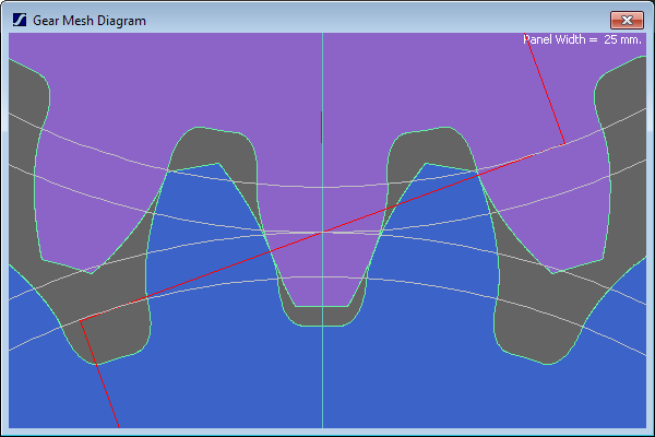
Is theta the pressure angle? Our gear design software won't even make the original gear with a pressure angle of 10° - the tooth profile just sort of turns inside-out. 20° works OKish, although the base circle is already within the working flank of the other gear:
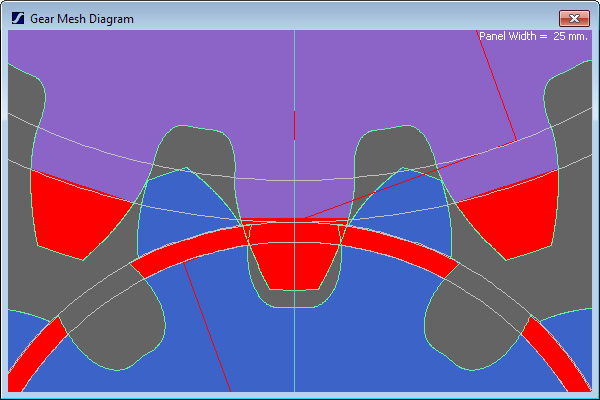
but if you reduce one gear to 10 teeth. the geometry fails again:
From a gear design perspective, fewer than 15T rarely works well - if you want a 2:1 ratio then I'd suggest going for at least 17:34, or try 19:38 if that doesn't work, and then adjusting the module to get the size you want. You should really use a full-fillet root to reduce the stress concentration (a pot drive is low-torque but 3D-printed parts are weak), and you may then need to adjust the addendum and dedendum offsets (the +2 and -2.5) to ensure the tip of each gear doesn't clash with the root fillet of the other.
I also can't see from your parameters what the helix angle is, which will affect the resulting profile - the above designs assume spur gears (which should be fine for your pot drive if the involute is done right - helical or herringbone gears are mostly used to reduce noise).
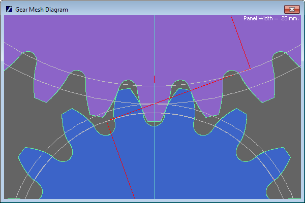
Here's 17:34, 1.5 module, 20°PA, 38.25 centre distance (you might actually want to run maybe 38.5-38.75 to ensure some backlash) and 1.0 addendum (+2) with 1.3 dedendum (-2.6), and a full fillet root:
Apr 07, 2016
10:03 AM
- Mark as New
- Bookmark
- Subscribe
- Mute
- Subscribe to RSS Feed
- Permalink
- Notify Moderator
Apr 07, 2016
10:03 AM
Alternatively, there's an old adage in modified cars: "Never build what you can buy".
Have you tried looking for off-the-shelf gears?
The accuracy (and hence the accuracy of movement transferred) will be far better than a 3D printer can achieve.
Apr 07, 2016
02:02 PM
- Mark as New
- Bookmark
- Subscribe
- Mute
- Subscribe to RSS Feed
- Permalink
- Notify Moderator
Apr 07, 2016
02:02 PM
Isn't the pressure angle for ("stub"?) gears 14deg?
Apr 08, 2016
03:33 AM
- Mark as New
- Bookmark
- Subscribe
- Mute
- Subscribe to RSS Feed
- Permalink
- Notify Moderator
Apr 08, 2016
03:33 AM
In my work, pressure angle is just a design variable - we have a number of 'standard' values but they're all higher than 14°. Working (as opposed to hob) pressure angles can often approach 30° for motorsport spur gears, although mainstream automotive helical gears are typically somewhat lower.
That may well be a standard somewhere, though!
Apr 08, 2016
06:43 PM
- Mark as New
- Bookmark
- Subscribe
- Mute
- Subscribe to RSS Feed
- Permalink
- Notify Moderator
Apr 08, 2016
06:43 PM
I just seem to remember the standard 2 being 14deg pressure angle, and 20deg P/A. But, I'm old and that was a long time ago..... 
Apr 08, 2016
06:49 PM
- Mark as New
- Bookmark
- Subscribe
- Mute
- Subscribe to RSS Feed
- Permalink
- Notify Moderator
Apr 08, 2016
06:49 PM
Well, I was close, but no cigar. It was 14.5deg P/A:
Apr 12, 2016
10:58 AM
- Mark as New
- Bookmark
- Subscribe
- Mute
- Subscribe to RSS Feed
- Permalink
- Notify Moderator
Apr 12, 2016
10:58 AM
you can get great gear models in native Creo/wildfire from Stock Drive Components - Small Mechanical Components: Precision Gears, Gear Assemblies, Timing Belts, Timing Belt Pulleys and Couplings - SDP/SI when you download the files there are parameters and relations in file that you can modify. I have had great luck in modifying the number of teeth and such.
Ron
Apr 07, 2016
09:47 AM
- Mark as New
- Bookmark
- Subscribe
- Mute
- Subscribe to RSS Feed
- Permalink
- Notify Moderator
Apr 07, 2016
09:47 AM
Hello Niels,
I attached a model of TPC but it is not in the student version.
Kind regards.
Denis.
Apr 08, 2016
05:30 AM
- Mark as New
- Bookmark
- Subscribe
- Mute
- Subscribe to RSS Feed
- Permalink
- Notify Moderator
Apr 08, 2016
05:30 AM
Thanks for all the replies...
-As much as I'd love to use something like 17/34 I just don't have the room for it in the setup...
-The reason I haven't gone for simply buying the gears is because the setup for the pendulum is already mostly finished, this means the pendulum axis is 7 mm and the encoder axis is 6 mm diameter, the smallest i could find is a gear with an OD of 12 mm for an inner bore of 6, which i would need to double to get to 2/1 ratio...
Once again simply don't have the room for it.
However If i could make a smaller version and 3D print it I could simply leave a section of the gear out to create room, since the pendulum would only move 20° or so in each direction.
- The reason I wanted to do this with helical gears is because they have a larger contact surface, which would be better for the transfer of these small angles that constantly change direction I would think.
I guess I will need to try it with regular spur gears, or simply try to find a way to put the encoder in line with the pendulum axis and lose the multiplication factor.
Thanks,
Niels
Apr 08, 2016
09:44 PM
- Mark as New
- Bookmark
- Subscribe
- Mute
- Subscribe to RSS Feed
- Permalink
- Notify Moderator
Apr 08, 2016
09:44 PM
How about thread and pulleys? OTOH, a linkage could also be used with any non-linearity taken out by software.
Apr 11, 2016
02:47 PM
- Mark as New
- Bookmark
- Subscribe
- Mute
- Subscribe to RSS Feed
- Permalink
- Notify Moderator
Apr 11, 2016
02:47 PM
"I don't have room for 17/34" doesn't make sense - just make the module smaller... (and for the same pitch diameters, i.e. same ratio and centre distance, a higher tooth count will reduce the OD of the gears as the teeth will be shallower).
Having said that, depending on the accuracy of movement you need, I suspect that the resolution of a 3D printer may cause problems and I'm not sure whether going to helical gears will help. I like the suggestion of the thread and pulleys, or a linkage.
What is your centre distance (how far apart are the shafts) and what package limitations do you have around them?
Announcements
Top Tags
