
Turn on suggestions
Auto-suggest helps you quickly narrow down your search results by suggesting possible matches as you type.
Showing results for
Please log in to access translation
Turn on suggestions
Auto-suggest helps you quickly narrow down your search results by suggesting possible matches as you type.
Showing results for
Community Tip - Want the oppurtunity to discuss enhancements to PTC products? Join a working group! X
- Community
- PLM
- Windchill Discussions
- Did You Know? Viewing 3D Models in PTC Creo View
Translate the entire conversation x
Please log in to access translation
Options
- Subscribe to RSS Feed
- Mark Topic as New
- Mark Topic as Read
- Float this Topic for Current User
- Bookmark
- Subscribe
- Mute
- Printer Friendly Page
Did You Know? Viewing 3D Models in PTC Creo View
Jun 03, 2014
10:33 AM
- Mark as New
- Bookmark
- Subscribe
- Mute
- Subscribe to RSS Feed
- Permalink
- Notify Moderator
Please log in to access translation
Jun 03, 2014
10:33 AM
Did You Know? Viewing 3D Models in PTC Creo View
The ‘Did You Know?’ series focuses on providing PTC Windchill users with informative, “how-to” tips to help them get the most out of their software. PTC Windchill includes integrated 3D Model viewing capabilities with PTC Creo View. Today, we will explore the different ways in which you can view and interact with 3D models in PTC Creo View.
Before we get started, it’s worth noting that PTC Creo View allows users to select different 3D scene navigation methods including; “PTC Creo”, “CATIA v5 compatible” and “Product View”. These methods are selectable from the “File -> Options -> General -> Navigation -> Navigation Model” option settings. This article is written using the default setting of “PTC Creo” for the navigational model.
Set-Up
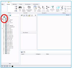
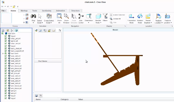
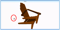
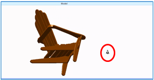
To get started, you’ll need to open a model within PTC Creo View. To do this, go to “File/Open”, select “All Types” below the “File Type” dropdown, and choose a model. In this example, we are going to follow along using a chair assembly. At first, the screen will appear blank. This is the default behavior which speeds up the part loading process. The model tree on the left allows you to interactively set the visibility of the assembly components. To make the full 3D model appear, select all of the boxes in the left column menu by clicking the top box in the upper corner. If you want your models to always display when loaded, you can configure this in the Creo View options menus.
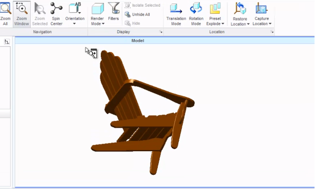
When viewing and interacting with 3D models, the most frequently used operations are “rotate”, “pan”, and “scale”. All of these operations have a virtual camera in common that looks at the 3D models and reflects what it “sees” in the main display window. Let’s experiment with these various viewing options plus a few others.
Rotating/Spinning Chair
Let’s start with “spinning”. To do this, click down on the scroll wheel and move your cursor in the direction that you want the model to rotate. By default, the model will continue to spin. To stop the rotation, click any of the mouse buttons. If you don’t have a scroll wheel mouse (i.e., a laptop) you can use the middle mouse button and trackpad input, as well.
Flying
Next, let’s “fly” about the model. This mode of 3D scene navigation enables you to bring the model closer or farther from your view and to move to the left and right. At first this may seem a little tricky, but once you’ve worked out the basics, it allows you to smoothly interact with and view the model by moving your mouse in the corresponding direction. To familiarize yourself with these motions on screen, right click and hold the mouse button. The cursor changes from the normal 2D arrow to an icon of a spaceship to remind you that you’re in fly mode. Moving the mouse up brings the model closer to you, moving it down pushes the model away, moving it right moves the model to the left, and moving the mouse to the left brings the model to the right.
Panning & Zooming
Next, let’s practice “zooming” (also known as scaling) the view of the model and panning the location of the model. There are multiple ways to zoom in and out; the easiest way to is to use the scroll wheel to increase or decrease the scale factor. Another method is to press and hold the control key while pressing and holding the scroll wheel in place and moving the mouse. If you don’t have a scroll wheel mouse press and hold the middle mouse button and the control key while providing trackpad input. Note that for all of these methods, the model will zoom away from the current location of the mouse in the view window. So if you want to zoom directly to the center of the model, move the mouse to the center of the window. Alternatively, you can use the “Zoom Window” feature in the navigation bar. With the mouse in the main 3D viewing pane, use the left mouse button to drag a selection region over the object and then select “Zoom Window.” This will zoom to the selected location and center the view over that region. If you want to reset the view, use “Zoom All” to make the entire model visible on the screen again. To “pan” the object about the viewing window, press and hold the shift key and the scroll wheel at the same time while moving the mouse. Again, if you do not have a scroll wheel, hold the shift key while holding the middle mouse button and move the mouse or use the trackpad.
Render Color and Transparency
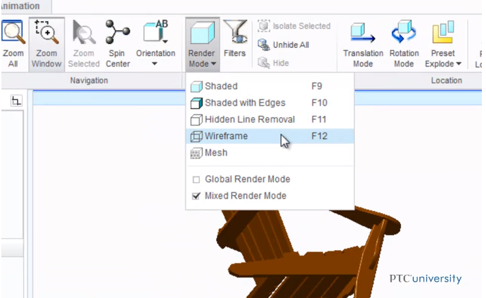
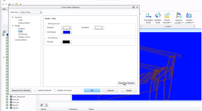
“Rendering” is the process of making the objects in the 3D world visible. Like an artist renders a painting or drawing, PTC Creo View takes into account object shapes and colors, lighting conditions, and the location of the virtual camera. There are multiple options for rendering the color and display type. To change the model display, select the “Render Mode” button in the navigation bar. In this example, I’m changing the chair model from “Shaded” to “Wireframe”. To change the background color in the main window, right click and select “View Settings” at the bottom of the pop-up menu. This brings up the Options dialog box. In the left menu column select “Color” below the “Model” header. Within the center menu area, select “Wireframe” as the background (since that is how we are currently rendering), select a color, and then click “Okay” and “Apply”. To change the color back, click “Reset to Default” and click “Apply”. Close out of this screen to return to the main viewing window.
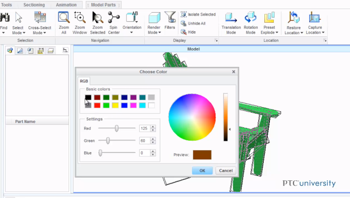
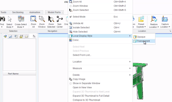
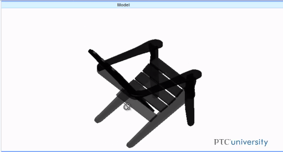
To change the color of the actual model, first change the “Render Mode” back to “Shaded”. Select the entire feature again, right click, and select “Color”. In this example, I am changing my chair from green to black. Should you want to add transparency, highlight all of the features, right click your mouse, and select “Local Display Style” and “Transparent”.
Changing Orientation
Sometimes, it’s useful to look at an object from a very specific set of viewing conditions -- for example, from the side, top down, or off axis. This is known as “changing orientation”. If you wish to change the orientation of the model, select the “Orientation” button in the navigation bar and choose any of the pre-defined options. Alternately, you can customize your orientation by clicking “Customize” and “New”. Then, save the model with a unique name. Now, no matter how your model is orientated you can always go back to a previously saved orientation. To wrap this up, save the current view of your model by clicking “File”, select “Save Current View As”, select “As an Image File”, and name the model.
To walk through these steps following the PTC University video tutorial in action (An Introduction to Viewing 3D Models in Creo View“), sign-in or create an account on the PTC University Learning Exchange .
Labels:
- Labels:
-
Other
0 REPLIES 0


