- Community
- Creo+ and Creo Parametric
- 3D Part & Assembly Design
- Sheetmetal bend
- Subscribe to RSS Feed
- Mark Topic as New
- Mark Topic as Read
- Float this Topic for Current User
- Bookmark
- Subscribe
- Mute
- Printer Friendly Page
Sheetmetal bend
- Mark as New
- Bookmark
- Subscribe
- Mute
- Subscribe to RSS Feed
- Permalink
- Notify Moderator
Sheetmetal bend
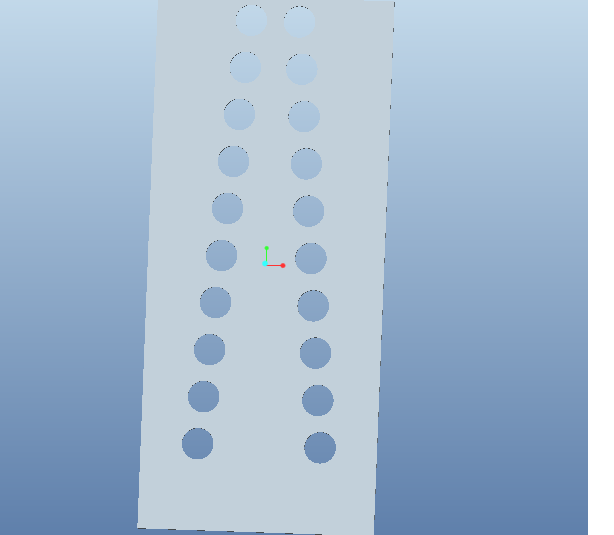
How to bend rectangular block to cylinder block ?
This thread is inactive and closed by the PTC Community Management Team. If you would like to provide a reply and re-open this thread, please notify the moderator and reference the thread. You may also use "Start a topic" button to ask a new question. Please be sure to include what version of the PTC product you are using so another community member knowledgeable about your version may be able to assist.
- Labels:
-
Sheet Metal Design
- Mark as New
- Bookmark
- Subscribe
- Mute
- Subscribe to RSS Feed
- Permalink
- Notify Moderator
do you have an image of what you are trying to bend? Are you roll a sheet into a cylinder? If that is the case have you tried creating the cylinder first then unbending it to make it flat?
- Mark as New
- Bookmark
- Subscribe
- Mute
- Subscribe to RSS Feed
- Permalink
- Notify Moderator

- Mark as New
- Bookmark
- Subscribe
- Mute
- Subscribe to RSS Feed
- Permalink
- Notify Moderator
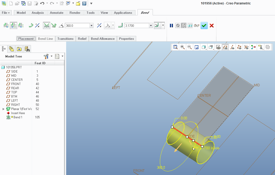
You can select the bend option use one of the edges you want to bend and then specify a 360 degree bend and use the inside circumfrence as the bend radius. Its probably not the best way to create the part but it should work. Of course this could be dependent on what version of Proe/Creo you are running. It may not be this simple in older versions of Wildfire.

- Mark as New
- Bookmark
- Subscribe
- Mute
- Subscribe to RSS Feed
- Permalink
- Notify Moderator
The problem is that you cannot simply mate the ends and let the bend radius be determined by the software. And a quick calculation also won't yield perfect mating because of the deformation (stretch and crush) of the metal. To calculate the full finished diameter, you will have to add the bend allowance factors into the calculations. I haven't done it but it should be possible to write that into relations.
One thing I learned not long ago about sheetmetal; you can make a surface model and then thicken it. You will end up with a very similar, if not the same geometry.
But for this; in sheetmetal, I would revolve the first surface. Apply a seam; unbend it; add the holes; and bend back.
- Mark as New
- Bookmark
- Subscribe
- Mute
- Subscribe to RSS Feed
- Permalink
- Notify Moderator
- Mark as New
- Bookmark
- Subscribe
- Mute
- Subscribe to RSS Feed
- Permalink
- Notify Moderator
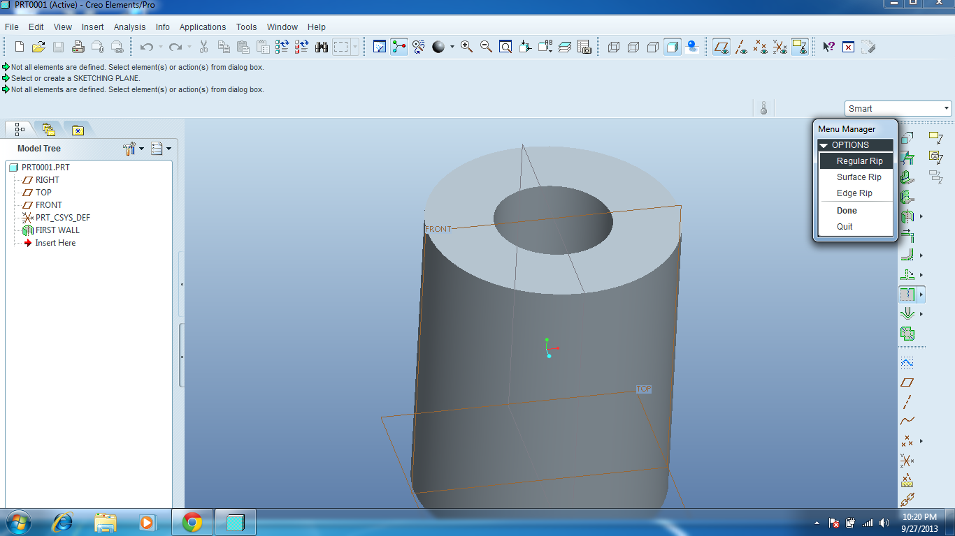
I created revolve wall as my first sketch, then if i follow second of your step I ma not able to complete the sketch (Rip). Find the image & help me ..which option i should go with ?
- Mark as New
- Bookmark
- Subscribe
- Mute
- Subscribe to RSS Feed
- Permalink
- Notify Moderator
No sketched rips in your version? I just sketched a line on one of the default planes and it projected in the cylinder. Will a regular rip let you do that?
- Mark as New
- Bookmark
- Subscribe
- Mute
- Subscribe to RSS Feed
- Permalink
- Notify Moderator
instead open circle's extrusion can also work...if you want to avoid sketched rip?
- Mark as New
- Bookmark
- Subscribe
- Mute
- Subscribe to RSS Feed
- Permalink
- Notify Moderator
True, if you want to define a default gap.
- Mark as New
- Bookmark
- Subscribe
- Mute
- Subscribe to RSS Feed
- Permalink
- Notify Moderator
Does it NEED to be in sheetmetal? Maybe use a spinal bend? Then it's easy to calculate the radius by the developed length (circumference). ![]()
- Mark as New
- Bookmark
- Subscribe
- Mute
- Subscribe to RSS Feed
- Permalink
- Notify Moderator
I was waiting for that one, Frank ![]() However, using the revolve in sheetmetal will let you easily manage the ID or OD. If you need control of the angle where features are located, you can use a reference dimension in the flat state to specifically locate features at the appropriate clocking angle.
However, using the revolve in sheetmetal will let you easily manage the ID or OD. If you need control of the angle where features are located, you can use a reference dimension in the flat state to specifically locate features at the appropriate clocking angle.
I bet there are a dozen ways to accomplish this and still end up with a sheetmetal part if you so desire.
Often the problem is that someone wants to "help you" by providing the flat state and you get to reverse engineer it. That's the only reason I mentioned the bend allowance calculation method.
- Mark as New
- Bookmark
- Subscribe
- Mute
- Subscribe to RSS Feed
- Permalink
- Notify Moderator
Ahhh. I'm still a novice at sheetmetal. Gonna have to try that, thanks! I'm sure doing that is tough, as the K-factor realistically changes with each lot of metal, based on the temper.
- Mark as New
- Bookmark
- Subscribe
- Mute
- Subscribe to RSS Feed
- Permalink
- Notify Moderator
Antonius,
" ...To calculate the full finished diameter, you will have to add the bend allowance factors into the calculations."
that's exactly what is needed to reach full 360 deg cylinder, and hope this is simple enough.
R(neutral axis) = 2*Pi / [Length of the flat piece]
R(internal) = R(neutral axis) - K*Thickness =>
R(internal) = 2*Pi / [Length of the flat piece] - K*Thickness
If you know K - factor (and you do know it) just define Inside Radius of a "roll bend" by relation from the abowe. Hope it should make full fit.
Regards
- Vlad
- Mark as New
- Bookmark
- Subscribe
- Mute
- Subscribe to RSS Feed
- Permalink
- Notify Moderator
Thanks Vladimir, for spelling that out.
- Mark as New
- Bookmark
- Subscribe
- Mute
- Subscribe to RSS Feed
- Permalink
- Notify Moderator
Thanks for your reply . I have tried in creo elemnts pro , but i am not able to get the desired result . can u please create a part model & share it with me ? And it should be from rectanglular to cylindrical
- Mark as New
- Bookmark
- Subscribe
- Mute
- Subscribe to RSS Feed
- Permalink
- Notify Moderator
There's a lot of good info here, I'll bookmark it. Thanks guys! ![]()


