1-Visitor
December 9, 2014
Solved

Filling gaps on surface profile

  • December 9, 2014
  • 2 replies
  • 13011 views

I wanted to create an irregular shape of human disc using the surface feature. I manage to construct the shape as per the sequence below:

1) Boundary blend at the wall area

2) Boundary blend at the top surface

3) Boundary blend at the bottom surface

ivd_iso_withsketchline.jpg

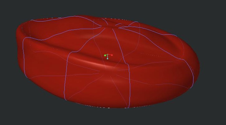
The blue line is the sketch reference used for the boundary blend feature.

ivd_iso.jpg

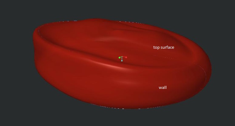
The final shape that I manage to construct.

I wanted to SOLIDIFY the image so that I can assign material properties to the structure -- but, it failed. I assumed it may be caused by gaps coexisted between the TOP - WALL - BOTTOM boundary. So I figured maybe I can export this file to .stp file, reimport the file with PTC Parametric and utilise the IDD (Import Data Doctor) to close any possible gaps.

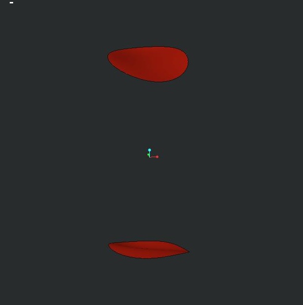
However, when exporting the surface to .stp (or iges.) format, it only export the little two circle (see image below) which was created using style > surface feature. WHY WHY WHY OH DEAR LORD is this happening? Been working on this for weeks and it's driving me crazy! Is there any way I can convert the boundary blend surface as SURFACE to be exported as STP file?

prt0002.jpg

ivd_iso_withnohiddenline.jpg

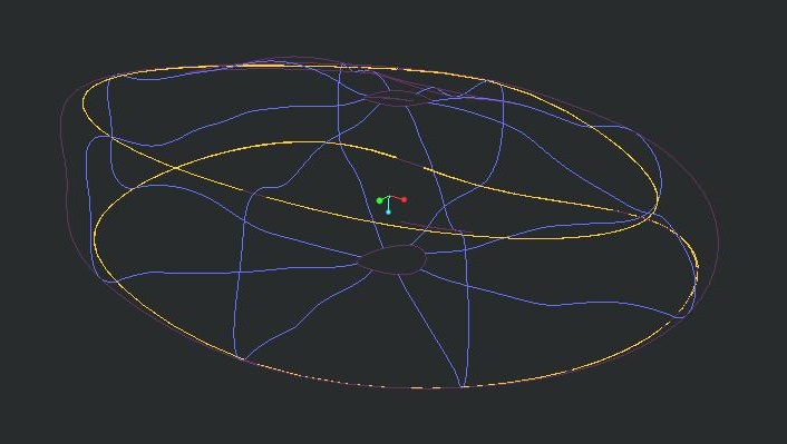
Here is the wireframe view of the above model.

Please, help!


This thread is inactive and closed by the PTC Community Management Team. If you would like to provide a reply and re-open this thread, please notify the moderator and reference the thread. You may also use "Start a topic" button to ask a new question. Please be sure to include what version of the PTC product you are using so another community member knowledgeable about your version may be able to assist.
Best answer by TomD.inPDX

Well, I did say it was a trick; not necessarily a solution.

However, by the same token, you can place a datum point in the middle of the hole and do the same thing.

Add tangency at the edges of the bounding surface and put a pin in it.

The point can be located by drawing a datum curve between two opposite vertices. Then place a point at 0.5 ratio along the curve. If you don't like the 1st result, you can tweak the points location or the shape of the datum curve, which also can be managed with tangency.

2 replies

24-Ruby III
December 9, 2014

Hi,

I guess that there are no real gaps in your model. Your model consists of 3 separate quilts. To be able to solidify the model, you have to merge 3 quilts into 1. Simply select two quilts and apply Merge command. You will need 2 Merge features to get the requested quilt.

Martin Hanak

makiah1-VisitorAuthor
1-Visitor
December 10, 2014

Hi Martin,

Thank for your enlightenment. I manage to merge to bottom-to-wall quilt. But when I merge the top-to-wall quilt, the top surface was deleted.

aftermerge.jpg

Zoomed up image of the top-to-wall boundary is as below:

gap2.jpg

Seems like some area are intersecting, while some other area are the gap. Tried the trim command, but doesn't change the end result.

24-Ruby III
December 10, 2014

Hi,

  • Merge command has two options - Intersect and Join. Did you try both of them ? There are "arrow", which enable to change side to be included in the merge
  • Did the second Merge fail ?
  • maybe you can redefine TOP quilt and use WALL boundary edge as reference instead of datum curve

Martin Hanak

Patriot_1776
22-Sapphire II
December 9, 2014

What is it, a bean bag chair?

makiah1-VisitorAuthor
1-Visitor
December 10, 2014

Just to answer your curiosity. it's the disc in between the vertebral bone.

l4l5segment.jpg

17-Peridot
December 10, 2014

I find playing with irregular surfaces absolutely frustrating in Creo.

What I normally end up doing is going after it in many different ways up to and including manipulating the default import features by changing the defaults prior to the import being done. It seems to heal a few issues but not much. In general, the export will come back the same or worse.

I think in your case, the technique is in the creation of the boundary blends and style features. You probably don't need the style feature in this case.

Can you post the model just before the merge function to see what others can do with this? Also state what version you are using... Creo 2.0, 3.0, or academic, trial, all change what people can do with it. An IGES and STEP export will be somewhat universal.

And the graphic "disconnects" may be just that, graphic artifacts. Creo is very particular about which edges you use to create things that are intended for merge.

It took years but I finally got IDD to zip up some edges... and I am beginning to understand some of it geometry error messages and how to resolve the. Again... not one solution, but many to try.