1-Visitor
October 27, 2014
Question

Large Deformation FEA

  • October 27, 2014
  • 4 replies
  • 12320 views

Hello all:

I've been working on getting FEA going for the small company I work for. I've encountered several challenges so far; I've learned a lot too. I'm finding it too easy to lead myself to believe every change I make is going to be the key to a more accurate simulation.

I'm trying to simulate destructive testing. I'd like to describe what I'm trying at this point and see if anyone has some suggestions on how I could improve. I'll more than welcome any questions, general discussion, or criticism. I'm just trying to learn more.

Here is the sample part I'm trying to simulate (2" x 2" x 3/16" tube). It is a weldment and I have bonded contacts on everything verified by the review geometry tool:

Sample+Part.PNG

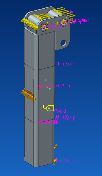
I have fixed displacement on the surfaces (lower bottom and middle, opposite side). I modified the mesh to be thin solid where possible. I also made the middle volume of the tube have smaller elements (0.3 in). I applied a load equal to just half of what I tested to be the max force of 6000 lbf (1500 lbf on each hole).

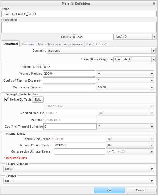
My material definition is below. The only other thing I specify here is the user defined property of the modulus of rigidity (11,600 ksi).

Material+Definition.PNG

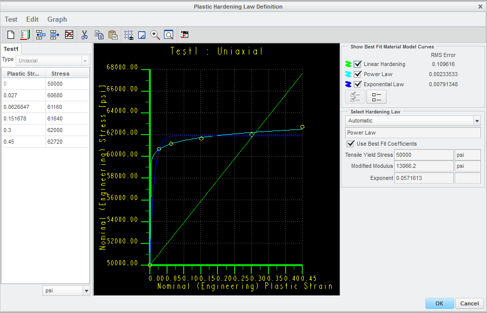
One of my big challenges has been getting a material curve that seems reasonable. I'm sure this could be a discussion on its own. Here is my material hardening curve:

Plastic+Hardening.PNG

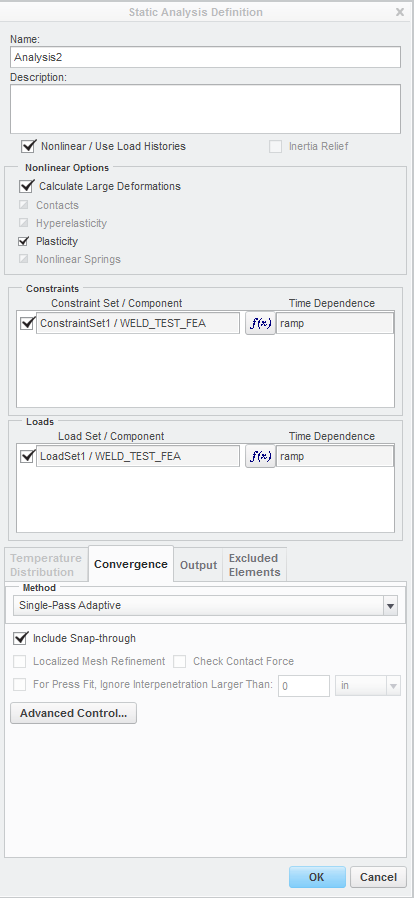
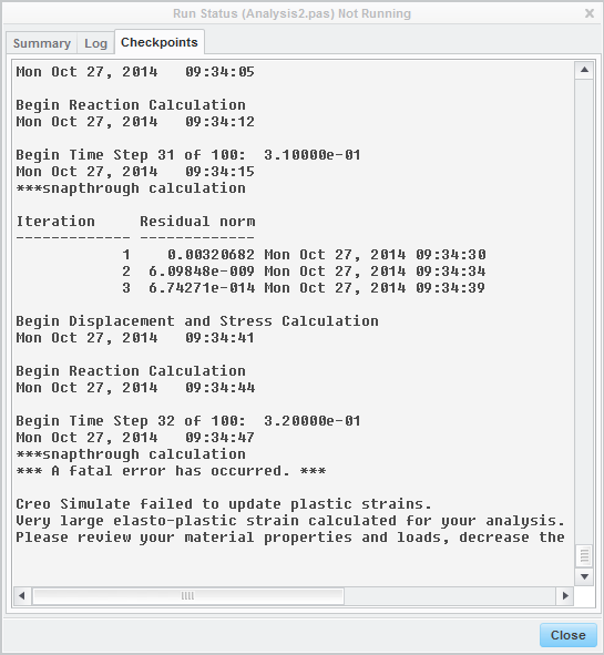
I've been running a staic analysis. I've tried with snap-through and without. I see little to no difference. I've tried running user defined output steps varying from 11-501 with little difference. Here is the analysis I run:

Static+Analysis.PNG

So when I run this, at the previously stated half of max load, the simulation fails at step 32 of 100:

Run+Status.PNG

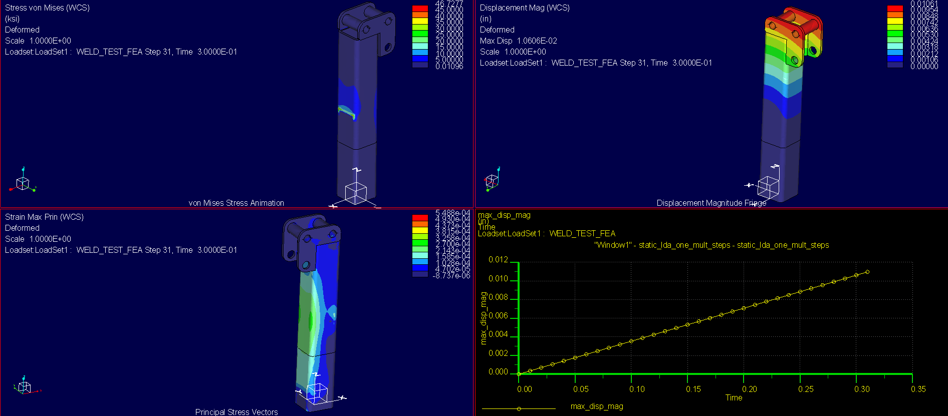
My results show a barely deformed sample with less than plastic deformation stress and very little strain:

Results.PNG

If anyone has suggestions or general input about what I'm seeing here, I'd like to hear it!

Thanks for taking the time to look at this!


This thread is inactive and closed by the PTC Community Management Team. If you would like to provide a reply and re-open this thread, please notify the moderator and reference the thread. You may also use "Start a topic" button to ask a new question. Please be sure to include what version of the PTC product you are using so another community member knowledgeable about your version may be able to assist.

4 replies

2-Explorer
October 27, 2014

Can you upload your model? I want to dig-through it first.

ChrisW1-VisitorAuthor
1-Visitor
October 27, 2014

Thanks for looking Shaun. Let me know if this isn't what you're looking for.

2-Explorer
October 27, 2014

Are components 711959800. Hinge_weld, and Hinge_Joint all welded together? Does that applied load always act along the x-direction, even as the tube deforms?

2-Explorer
October 27, 2014

I'll need to do some more testing when I get time, but my initial thought is that the issue is due to sharp change in the tangential stiffness of your material when it goes into the plastic region. This is typically handled via the snap-through effect, but there currently is an (apparent) bug with the span-through effect in Creo 2.0 and 3.0. I changed your elastoplastic material properties to linear-hardening with a tangent modulus that is 10% of your Young's Modulus and it solved:

Weldment_FEA.png

Also, you're using fixed-constraints (i.e. the surface cannot move at all); is this realistic? How was the physical test set up? Were supports welded to the tube in these locations?

ChrisW1-VisitorAuthor
1-Visitor
October 28, 2014

Thanks Shaun.

I went ahead and ran the linear hardening as you specified. I did the same load positioning as I had before, but I used two 3000 lbf loads to get more deformation as I saw in the real tests. Here's what I got, similar to yours:

Linear+Hardening.PNG

That just doesn't make sense to me. Linear hardening should give more plastic deformation than my original material curve, right? And why do we have these off-the-charts stresses with very little strain?

Here is some real data I collected for the tube to show you what I'm shooting for:

Weld+Test.PNG

I was going to run a contact analysis, but quickly figured out that won't work for nonlinear simulation in Creo 2.0. I just drop the sample into this larger tube that is reinforced. Here is a model of the test stand (It is suppressed in the assembly I uploaded):

Test+Stand.PNG

Thanks,

Chris

1-Visitor
October 28, 2014

Chris,

I have not looked at your model, but I'd like to share some of my experiences:

  • Singularities such as reentrant corners will make it difficult to for an elasto-plastic analysis to converge. If you expect plastic deformation in a portion of the model but you have singularities elsewhere, create a volume region where you want to analyze yield and use elasto-plastic properties only for that region. Make sure that the volume region is large enough so that the stress levels at the region's boundaries are below yield. Use linear material properties elsewhere. If you have singularities, it is a good idea to use a AutoGEM control on a volume region to exclude those elements from convergence, otherwise the solver will waste time on increasing P-level at those singularities.
  • Note that the material properties you enter, for the elasto-plastic material only account for the plastic strain, not the elastic strain. This mean that if the yield stress is 250 MPa, then the first point of the curve that you enter should be (0,250). I.e. zero plastic strain at 250 MPa. Additional points should only account for the increase in plastic strain vs. true stress.
  • Solving non-linear problems, for example elasto-plastic analyses is more sensitive to the mesh. If it is possible, try to use "Mapped mesh", "Prismatic elements" etc.
ChrisW1-VisitorAuthor
1-Visitor
October 28, 2014

Thanks for the info Mats.

  • That's a good idea to use a volume region and separate it as an elastoplastic material. However, this is just a very small sample that I'm trying to use for calibration of simulation. I feel that once I get into much more complex structures that creating these volume regions would get into too much guesswork. You have said a lot about singularities. Do you refer to singularities just as sharp corners?
  • I understand the plastic curve, but in reference to true stress, why is there no function allowing stress to hit a vertical tangent? As in, after I hit about 20% elongation, I would prefer to see a high stress region that I would understand to be the point of failure. I'm not sure if I'm looking at that right.

Thanks,

Chris

1-Visitor
October 28, 2014

Chris,

Any singularity in the solid with non-linear material property, that result in a stress that does not converge is problematic. I see now that your model has a few singularities like that.

Around the top of the structure, around the welds etc. there are a few reentrant corners. Typically I would create rounds to remove those singularities. Or, and this is what I did, create a volume region of this portion of the structure, and assign linear material properties to this region. Also create an "Isolate for exclusion" AutoGEM control, for this volume region, so that the solver won't waste time to increase P-level where you have singluarities...

Other singularities are the constraints who prevent tangential displacement. This means that there is an abrupt change in stiffness between the perfectly rigid constraint and the elasto-plastic steel. Is this realistic? In my model I have released tangential displacement, so as to mimic a contact.

As Shaun mentioned above, your material property, with a significant drop in tangential stiffness looks suspicious. I changed the property as Shaun did. The stress-strain functions available (linear hardening, power law, exponential law) do not allow the stress-strain curve to become vertical I guess because that is not realistic. The tangential stiffness (true stress, true strain) is typically finite, and if anything, it becomes lower as the point of failure is approached. As is the case with exponential and power law hardening.

I used symmetry to reduce the number of elements. The geometry, loads and constraints are symmetric, right?

I removed your "thin solid" AutoGEM control; I got some meshing problems. It could be because I added another volume region. Initially, I'm not interested in accuracy, I just want the analysis to run without error.

The model that I have uploaded seems to be able to run the analysis through, it's in load step 15 of 51, pass 2. I need to get back to work... I hope this helps.

/Mats L/Avalon Innovation/

ChrisW1-VisitorAuthor
1-Visitor
October 29, 2014

Shaun, Mats, Jonathan:

Thank you all very much for the insight! I have a lot more to experiment with now. This discussion has been very useful and I hope others benefit from it as well.

-Chris