2-Explorer
October 24, 2016
Question

Slot on circle surface

  • October 24, 2016
  • 5 replies
  • 11718 views

Hello,

l have some modeling problem and asking about help. See attached file (Creo 2.0)

l´m modeling slot on circle surface with a problem in transition between flat part and curved part.

Red marked surface doesn´t looke fine ... l think something is wrong in my modeling procces (but what?).

slot_problem.JPG

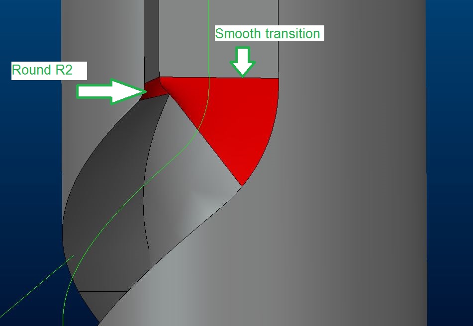
How to model it in order to use round feater on inner edge?

Is my technique correct? (using warp feater)

Thx for guidance

Regards

Milan Bonka

5 replies

1-Visitor
October 24, 2016

Based on a quick adjustment of the dimensions I'd say your dimensions for the slot are not appropriate for a smooth transition, the technique is fine.

1-Visitor
October 24, 2016

You need to adjust a few controls inside sweep feature.

Have a look on the attached image.

Hope this helps.

Capture.PNG

1-Visitor
October 24, 2016

Hi, I have had a little go at doing this feature. I created a sketch plane above the cylinder and sketched a trajectory, this is then projected onto the cylinder. Use a sweep on the end to create the slot profile and project this along your trajectory. I had some issues which you may need to address too, if the included angle is too great it will project around the other side of the cylinder too so don't take it right to the edge. I have attached a couple of screenshots to show what I mean. You shouldn't need to patch any rads in. If you included angle is too great then this may not work (show as about 45 deg. in my example)

Captureslot.PNG

Captureslot2.PNG

Patriot_1776
22-Sapphire II
October 24, 2016

Keep in mind, a milling cutter will almost always not create the geometry you model in this situation.  The deviation from what is modeled will depend on the size of the cutter vs. the modeled geometry, and the actual trajectory of the modeled geometry.

To create the actual "cut" geometry it can be an absolute PITA.

1-Visitor
October 24, 2016

In this case, the cut geometry will actually work; because a projected curve curve used as the trajectory, the sweep section's horizontal/vertical orientation will be controlled using the "Normal to surface" option (the surface onto which the trajectory was projected).  This means that the cutter axis will always go through the stock axis.  And since the section plane will stay normal to the trajectory, such sweep will faithfully represent a cut made by an endmill that moves along the stock axis while the stock is turning.

slot_cam.png

slot_cam2.png

Because of the limitation of the projection curve only working in the 1/2 of the cylindrical surface, using wrapped sketches to generate the trajectory curve might be preferable.

Patriot_1776
22-Sapphire II
October 24, 2016

Actually, that's totally incorrect.  The difference is that a cutting tool is a side-cutting device, and will remove MORE material that your cut, sometimes a LOT more depending on the sweep trajectory (the tighter the curve radii the bigger difference).  Take the trajectory and pattern a series of points along it at, say, .010" intervals.  Then pattern cylindrical cuts of the cutting tool size at every point and you'll see what I mean.

This is a known issue, and there is at least one thread dedicated to it. 

23-Emerald III
October 25, 2016

Here's a product idea for solid body sweep.

Cut using solid body motion (sweep) in Creo Parametric