1-Visitor
August 14, 2012
Question

Trying to learn Spine Bend

  • August 14, 2012
  • 4 replies
  • 9573 views

I'm certain that I can modify 2 straight developed cylinders into Spine Bend Features. I unfortunately don't understand the specific steps needed to build this.

Could someone help me with the details of how this would be done?

I believe I've seen a thread suggest that you would need a start and end datum. When the term datum is used do they by chance mean start and end curves?

I always error out when I try to follow the Spine Bend routine.

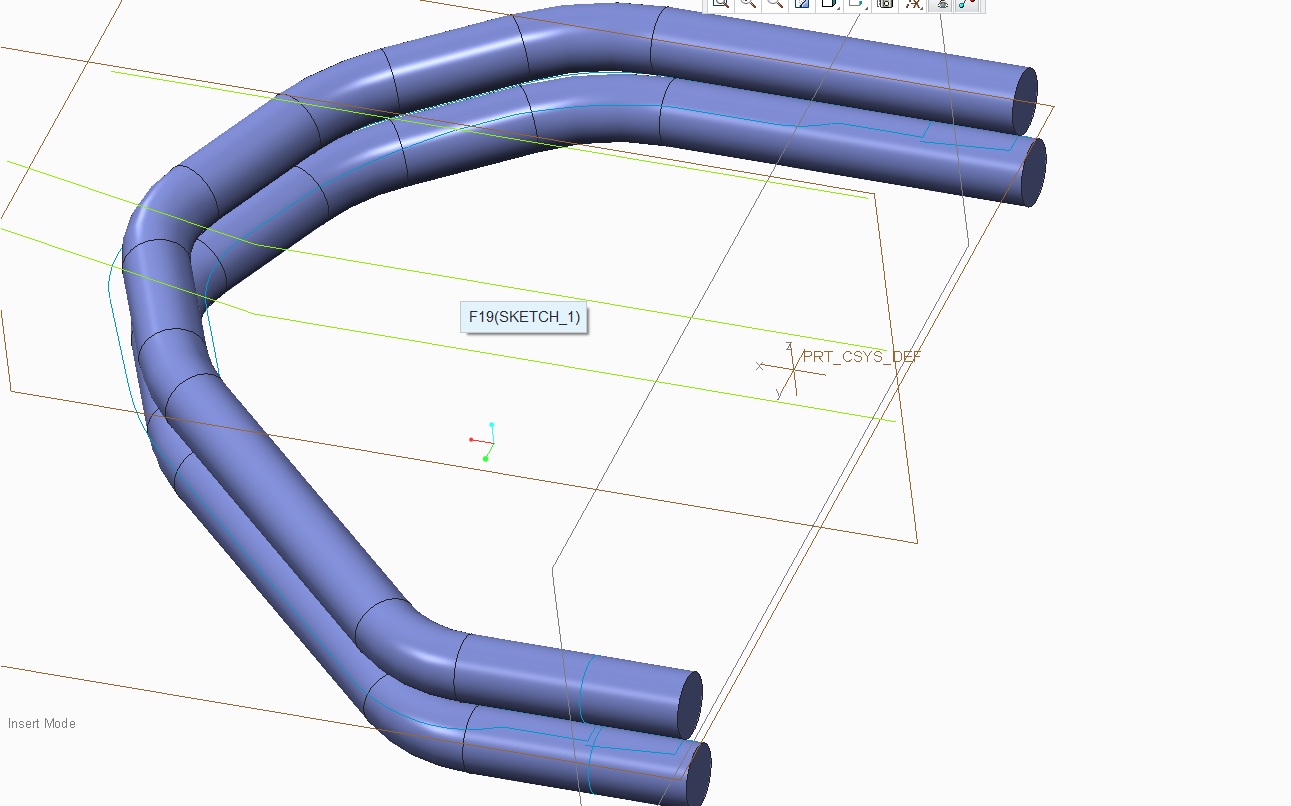
I will attach a picture of the model I am hoping to have bent.

Spine Bend.jpg


This thread is inactive and closed by the PTC Community Management Team. If you would like to provide a reply and re-open this thread, please notify the moderator and reference the thread. You may also use "Start a topic" button to ask a new question. Please be sure to include what version of the PTC product you are using so another community member knowledgeable about your version may be able to assist.

4 replies

17-Peridot
August 14, 2012

dellens1-VisitorAuthor
1-Visitor
August 15, 2012

I appreciate the attached video but I can't follow this through to the solution for my own application.

I don't understand how this function sets up in what you can and can not do. It appears that you can do very different types of applications but the key entries needed are quite confusing.

13-Aquamarine
August 15, 2012

Hi guys...

I can help with this. Spinal bend can create some cool geometry but it's not so well known for being accurate. It can actually stretch or compress geometry in unexpected ways. I will be happy to demonstrate this feature if you'd like. I can either do some powerpoint slides or we can just do a quick GoToMeeting.

The basics of a spinal bend are the curve itself (the "spine") and then two parallel planes or surfaces that define the area you wish to bend. You can bend an entire object or just portion. Let me know how you'd like me to explain this... I'm happy to use either method.

Thanks!

-Brian

Patriot_1776
22-Sapphire II
August 15, 2012

It's a powerful command, but a little tricky until you get used to it. The plane "defining volume to bend" means just that. For instance, if you have a tube with holes in it that's 10" long, and your 2 planes are 5" apart, that 5" will be stretched the length of that spine, however long that is. Conversely, if your planes are 20" apart, it will compact that volume along the spine length. So, to eliminate or minimize any distortion, make sure the planes are where you want them, and that your spine is the correct length (in this case, 10" total).

So, for the parts you see below, I made a sketch of the geometry I wanted. I knew that the legs would be made from an extruded shape, and then have a radial cut normal to the extrusion's centerline. Then, the legs would get bent, but I wanted to have the inside length of the bend remain the same and stretch the outer length. So, I created a datum curve of the geometry for both legs I wanted. Copied the inside curve segments I wanted to use as a spine separately for both legs as it's own curve. I then used an evaluate feature and a relation to drive the surfaces I extruded and merged with the radial cut. I did surfaces because I had 2 spinal bends to make, and it allows greater flexibility as when I'm all done with the spinal bends I can solidify them whereas if you're trying to bend a solid, you get EVERYTHING in that "volume to bend". Then I used 2 spinal bends to get the final geometry. I did this becase I have a family table with instances of this part in the raw, extruded length, with the straight legs length (for the vendor), and with the final bent length. It seems to have worked out very well as the vendor is really happy I can tell him the length of the legs to start with, and as you can see the geometry is correct for the cuts (normal to the sides not normal to the extruded centerline).

SPINAL BEND 1.JPGSPINAL BEND 2.JPGSPINAL BEND 3.JPGSPINAL BEND 4.JPG

Good luck!

dellens1-VisitorAuthor
1-Visitor
October 23, 2012

Hi Frank,

I'm sorry I'm very slow to get back to discuss your suggestion. Our company had a couple hot jobs that needed completed and we have been scrambling ever since. We had to complete these jobs in the CAD software which will be replaced for sake of time. Now that more time is freeing up I wanted to trace back.

This method appears to work very well I appreciate this suggestion. You appear to be the master of Spine Bends.

I would like to try applying this in my own application. I'll let you know how this turns out. It's quite possible that nothing will work.

Thank you for your help.

dellens1-VisitorAuthor
1-Visitor
October 23, 2012

I'm almost thinking that there is no possible Spine Bend solution for this application.

What this really needs to bend about is a sketch about the center datum. This means that the spine would not lie along the sweep that needs bent upwards.

In all the examples that I've seen the spine lies along the part that needs bent.

Patriot_1776
22-Sapphire II
August 24, 2012

Wow! A lot of views, but no comments?

17-Peridot
August 24, 2012

We are just in awe, Frank It's a perfect application for this type of command.

Patriot_1776
22-Sapphire II
January 16, 2013

More spinal bend fun. This time, I had a flex circuit assembly that needed to be in 3 different states: Flat, with just the leads bent (for soldering), and with the leads bent and bent in the final shape. It needed to be an assembly so that I could get different cross-sections for the different layers. So, I had to do 9 family table instances for the basic parts, then 3 different instances at the assembly level to get it all to work. Too bad you can't do a spinal bend on an assembly at the assembly level.

62-8768_I_10MM_FLX_BNT_LED-BODY.JPG