1-Visitor
February 20, 2015
Question

Non-symmetric results for symmetric model and load?

  • February 20, 2015
  • 17 replies
  • 24903 views

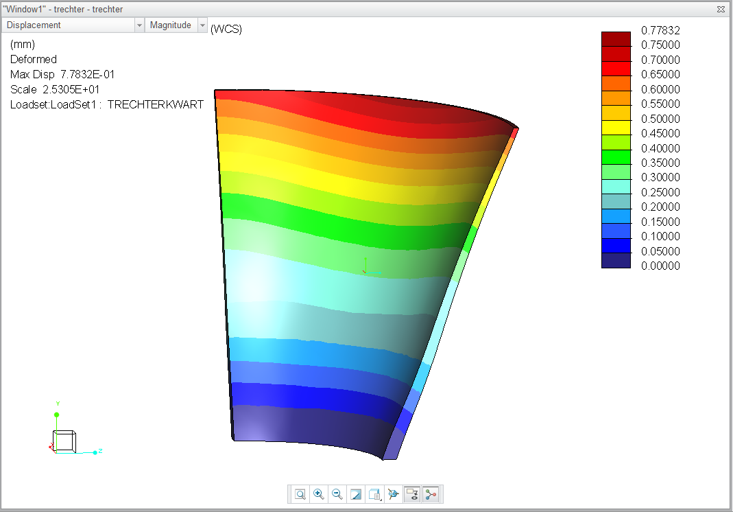
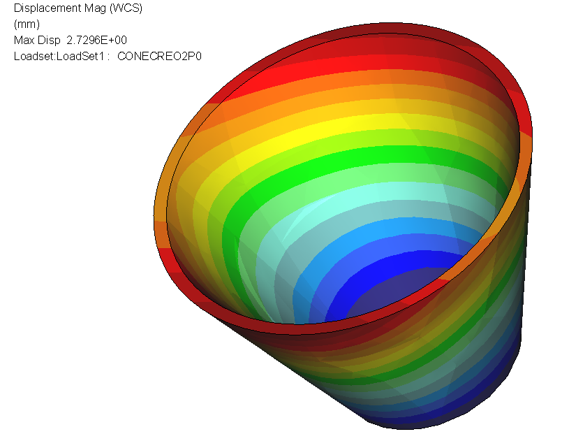
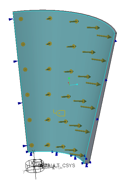
Why is it that displacement for a cone is not rotational symmetric for an internal pressure?

A sample model is attached (Creo 3.0) I've brought it back to the bare minimum. 1/4 cone, symmetry, default mesh etc.

It doesn't help if you refine to enormous amounts of elements, Large deformationm analysis makes it slightly better, but it is never right?


Why is that? it should not happen.

How do we solve this?


Extra: I've added a full 360 degree version in Creo2.0 format

resudisp.PNG


creo2version.PNGsimplecone.PNG

17 replies

1-Visitor
February 5, 2016

Creo3 m080 is available, anyone tested it yet on this problem?

ehaenen1-VisitorAuthor
1-Visitor
February 5, 2016

Agnes: Be my guest

And: Has anyone tried whether it was fixed in creo 2.0 M170?

Should be no problem because on december 28, 2015 Mark Fischer said in Enforced displacement, tangential direction, more than 1 revolution

That he would look into this.

He wrote:

Thank you for your post and I appreciate your feedback.  Comments like this are not taken lightly and I am looking into both issues referenced in the above thread (SPR 2848377 and SPR 2873817).

Surely by now Mark knows the status?

Erik

1-Visitor
February 10, 2016

Hi Eric,

I tested Creo 2 m180 and am very happy with the results; The strange effect halfway the cylinder is gone!

Yes, there is still deviation but it is smaller then the convergence criteria (2% in my case), even with default mesh settings.

Creo2m180_defaultmesh.jpg

With mapped mesh, you can do the same with much less elements, but you do see some deviation over each element. However, this deviation is also smaller then the convergence set. Following example has one half divided into 4 and the other divided into 8 elements. It seems you can control the result much better now with increasing element numbers;

Creo2_m180mapped8versus16elements.jpg

BUT, we saw before that one example can look fine, while another shape shows much bigger deviation, so it would be great if somebody else could confirm this.

1-Visitor
June 21, 2016

Hi,

geometry transfer from parametric to simulate is inaccurate:

kegel.jpg

30°, 60°, 90°, 120° etc.error expand

As assembly 180x2°:

Paulkegel_korrekt.jpg

ehaenen1-VisitorAuthor
1-Visitor
June 21, 2016

Most impressive about this is that PTC has not yet been able to offer a solution to what must be classified as a serious bug.

It's been 476 days since the SPR has been submitted by Agnes Uijttewaal.

I've been infortmed by a colleague out there that the bug is still present in the 4.0 sneak preview.

Bravo PTC, well done!

Trying not to sound disappointed after using the Simulate software and paying maintenance through various employers  for 24 years.

I don't consider it worth my time to help others solve problems through this forum if PTC does not show an effort to help (whilst being paid for it)

Thanks for people who helped me so far,

Regards

Erik

18-Opal
July 15, 2016

Hi all,

Let me provide an update to the issue.

In Creo Simulate, based on the component (solid or surface geometry) AutoGEM tries to create tetrahedral elements where applicable.  This is the default behavior.  Here is an image of the default mesh created in Simulate for the cone model provided.  There are 234 tetra elements created.

7-15-2016 3-36-33 PM.jpg

Now running the analysis, you will find the results do not match the expected max displacement of 2.367 mm as in the thread above (Abacus results).  Obviously, there is a discrepancy in the analysis.

An area we have been investigating was the defined size of the elements shown in the image above for this model.  Now Simulate does process the size of the elements based on a number of factors during AutoGEM - model size, size of thin walls, etc. The element size optimization helps provide accuracy in the results versus compute time needed to run the analysis.  In most cases, the element size optimization output is appropriate and helps provide accurate results.  However, in this example, due to the thin wall, we feel the size of the elements might need to be reduced beyond the optimized size produced from AutoGEM.  Development is investigating the algorithm and seeing if it can be tweaked to see how this will improve the results.....at the same time, not causing ill effects elsewhere.  By ill effects, I mean lengthening the process time for all analyses as a result of increased number of elements created by AutoGEM.  Note: this tweak would be a global setting, so we need to be cautious not to negatively impact Simulate. We will have more news on this upon completing our investigation.

Now for this model, we can show that reducing the element size can provide results closer to the expected max displacement.  To try this, you can add a Mesh Control Option - Max Element Size.  In my image below, I changed the max to 12 mm.  This will obviously increase the number of elements created.

  7-15-2016 4-02-40 PM.jpg

Running the analysis, the results are very closer to the expected max displacement.....off by ~1%.  This assumes the results shown above from Abacus were correct.

Another approach would be to add other mesh control options, such as Thin Solids.  This will create both brick and wedge elements.

7-15-2016 4-13-38 PM.jpg

Again the results are very close within 1% of the Abacus results.

In both these cases, the user would need to add the control options - thin solid or max element size.  To help influence the analysis without the need to add the options is the reason why we are investigating a tweak to the optimization algorithm for element size.

In Creo 4.0, we have added a new option which will help automate the process of creating Thin Solids.  This option is available under the AutoGEM Settings dialog and is called 'Create automatic thin solids'.

7-15-2016 3-21-32 PM.jpg

This can also be controlled by the config option - 'sim_auto_create_thinsolids'.  Either checking the box in settings (session only) or adding the config option (all session), during AutoGEM, where applicable, brick and wedge elements will automatically be created.  Note: this will not create a thin solid node in the model tree under AutoGEM Controls.  This can be tested in the Creo 4.0 Sneak Peek. Running the analysis with the checkbox selected will provide the following results.....which is less than 1% off the expected max displacement.

7-15-2016 3-22-21 PM.jpg

I hope this helps explain the situation and the steps you can use to obtain the desired results.  In the meantime, PTC is also looking to improve Simulate to obtain these results out of the box.

Regards,

Mark

ehaenen1-VisitorAuthor
1-Visitor
July 16, 2016

Dear Mark

Thank you very much for your detailed answer, but I'm afraid it is a typical case of: too little too late.

It's taken your company 17 months to provide me with the answer that I need a finer mesh. With your product placement (every good designer should be able to use this simulation tool) it is hard to convince your typical user that something easily recognizable (a round-ish thing that becomes un-round-ish with a uniform load) needs extra attention, and still trust results obtained for more realistic products like the one shown below, which is, by the way, not likely to mesh very well in thin solids.

thinsolid.jpg

  • If this is support, I consider it not present.
  • I've seen Jose Coronado's "PTC Creo Simulate Roadmap" of March 2016, containing not much more than cosmetic changes for Creo Simulate 4.0.

As far as I can tell PTC continues to be commercially interested in this product, but seems to have lost the will to back this with technical effort.

--> So why am I paying maintenance for a product that is not supported and not developed?

I regret to have to say that after being a very loyal customer for more than 20 years through various employers, I've informed my reseller two months ago that I will discontinue PTC maintenance as of September 6.

It's a shame.

Kind regards

Erik Haenen

1-Visitor
July 24, 2016

Erik,

revolve feature in STRUCTURE is inaccurate:

cylinder-torus.jpg

this "ERROR" is 30 years old.

Paul

1-Visitor
September 2, 2016

workaround:

fake of geometry to bezier.

example attached

Regards

Paul

1-Visitor
September 9, 2016

comparison bezier vs. revolve

(Creo Simulate 2.0 M080)

cone_spline.JPG

1-Visitor
September 9, 2016

Prefer Swept type mesh for rotational and cylindrical objects. Formation of element and nodes plays crucial role in analysis.

1-Visitor
September 11, 2016

"Formation of element and nodes plays crucial role in analysis"

yes, exactly

"Prefer Swept type mesh for rotational and cylindrical objects"

well, that is the problem

revolve of spline geometry only is correct: as bezier surface

13-Aquamarine
September 12, 2016

Paul Kloninger wrote:

"Formation of element and nodes plays crucial role in analysis"

yes, exactly

Well, yes and no...

To play devil's advocate a little, 1) Simulate (Mechanica) is supposed to remove the need for the user to 'worry' about the mesh so much; and 2) surely for a simple analysis such as this, with very smooth stress and displacement contours, even a very 'poor' mesh should give the correct result?  Particularly when looking only at displacement, for which a coarser mesh is traditionally considered adequate.

1-Visitor
November 24, 2016

1.JPG2.JPG3.JPG

It's difficult to attach the result files,so sorry! Remember to use cylinder coordinate when you check the displacement !!!

skunks
19-Tanzanite
March 3, 2017

bezier has exaktly 0%

example (bezier vs. revolve).

1-Visitor
June 20, 2017

Hi Erik

It seems as though the stiffness of elements is not being held constant during calculations.

If we take a simple example of a beam with constant area, its stiffness is AE/L, so stiffness is inversely related to length . As L goes up , stiffness goes down, so nodal displacements should increase. Also, we have applied pressure load, which should transform to perpendicular point load (P) at a beam end like this.(the beam becomes element edge) Delta should reflect the deformation.

6.JPG

In our cone model, even brick elements produce unequal edges, which are longer at center and shorter at ends.

7.JPG       y2.JPG

I tried the model in first reply(by Matts) which produced good results initially but deviated once the thickness became variable, so element area seems to affect the calculations as well. Maybe thats why it was suggested to use thin solids.


Lastly I tried the above scenario with a quarter cylinder using a similar setup.

Again, the tetras(default) create unacceptable output. Both prismatic elements and brick elements produced clean results possibly because element edge lengths are uniform.

However, tetra output quality gets better as mesh gets finer.

3_random.JPG

1.JPG2-mapped.JPG

Displacement graphs in tetra shows a very high variation(crest-trough) while the brick shows little change.

Tetra has a global peak at the center, which is not observed in bricks model. Also, the brick model is kind of repetition of a pattern which appears to depend on the no. of subdivisions.

4-map.JPG5-mapped_map.JPG


Just a hunch but if this is the case, the software should do some sort of "internal normalizing" before publishing the results. Inputs are welcome.