
Turn on suggestions
Auto-suggest helps you quickly narrow down your search results by suggesting possible matches as you type.
Showing results for
Please log in to access translation
Turn on suggestions
Auto-suggest helps you quickly narrow down your search results by suggesting possible matches as you type.
Showing results for
Community Tip - Want the oppurtunity to discuss enhancements to PTC products? Join a working group! X
- Community
- Creo+ and Creo Parametric
- 3D Part & Assembly Design
- Re: how to change default tolerance value in drawi...
Translate the entire conversation x
Please log in to access translation
Options
- Subscribe to RSS Feed
- Mark Topic as New
- Mark Topic as Read
- Float this Topic for Current User
- Bookmark
- Subscribe
- Mute
- Printer Friendly Page
how to change default tolerance value in drawing
Nov 06, 2014
03:27 AM
- Mark as New
- Bookmark
- Subscribe
- Mute
- Subscribe to RSS Feed
- Permalink
- Notify Moderator
Please log in to access translation
Nov 06, 2014
03:27 AM
how to change default tolerance value in drawing
Hello,
just wondering how the default tolerance value works at new created dimension in drawing. Since i use mostly the +- symetric - would it be possible to set the default tolerance (maybe in drawing setup file) value this way?
Thanks in advance
T.
Labels:
- Labels:
-
2D Drawing
- Tags:
- drawing
14 REPLIES 14
Nov 06, 2014
02:57 PM
- Mark as New
- Bookmark
- Subscribe
- Mute
- Subscribe to RSS Feed
- Permalink
- Notify Moderator
Please log in to access translation
Nov 06, 2014
02:57 PM
You can set this in config.pro. It seems to be very convoluted but once set, it works.
For some reason, it has to be in config.pro, and not changed in the options editor.
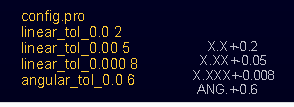
The values are set to a factor of 1000x. Drawings take on whatever the current config.pro settings are.
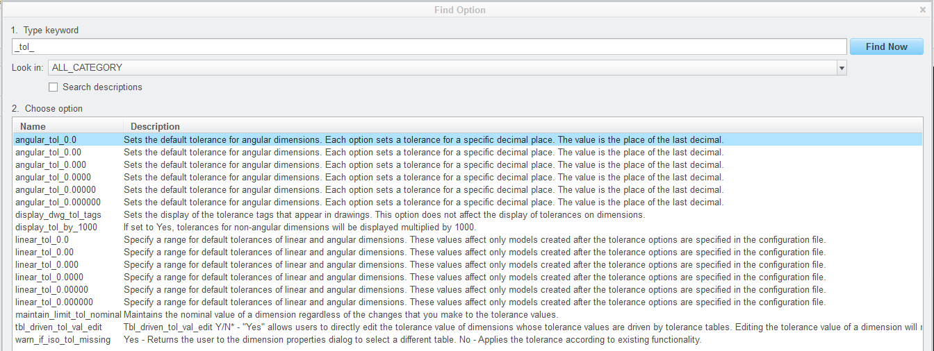
These are the valid options in config.pro (linear and angular):
I used whole numbers in the settings in config.pro. These are the default ones that show up on the screen.
If the current default_dec_places is 3, the .008 will be used on drawing dimensions as well.
If, like me, you use default decimal places is 4, I cannot seem to get these to be recognized by default. I suppose I need to file yet another support case. Config.pro is recognizing the linear_tol_0.0000 50 but the actual value comes in at .0001 in both drawings and models.
Nov 06, 2014
03:21 PM
- Mark as New
- Bookmark
- Subscribe
- Mute
- Subscribe to RSS Feed
- Permalink
- Notify Moderator
Please log in to access translation
Nov 06, 2014
03:21 PM
I created a case for using values greater than 9 in these default toerlance settings. Options shows it is accepted but in reality, it doesn't work.
Use case, my drawings use 3 digit dimesnions but I want to see 4 digits when modeling. I want the default tolerance value to be .005(0)". I can't do that with 4 digit dimensions!
Nov 07, 2014
12:29 PM
- Mark as New
- Bookmark
- Subscribe
- Mute
- Subscribe to RSS Feed
- Permalink
- Notify Moderator
Please log in to access translation
Nov 07, 2014
12:29 PM
Support in this case is becoming very frustrating. I am being told that indeed you cannot apply a value greater than 9 (DUH!). I did not hear that this is functioning according to specifications.
Support also came up with the fact that linear_tol is a valid option although it does not show up in the options>find dialog. Support said they will file the SPR for the missing option.
I see this being escalated! There is no reason the option linear_tol_0.0000 cannot accept .0050 as a value. Even the dialog is accepting it in options. But it is not being carried forward to newly created dimensions.
I even asked specifically if the linear_tol (and angular_tol) were WF/Pro-E options that were being replaced with no answer. I only received the link to the options guide that still includes the two in Creo 2.0.
Nov 06, 2014
04:36 PM
- Mark as New
- Bookmark
- Subscribe
- Mute
- Subscribe to RSS Feed
- Permalink
- Notify Moderator
Please log in to access translation
Nov 06, 2014
04:36 PM
Can you try these in your config.pro:
default_dec_places 4
linear_tol 1 0.2
linear_tol 2 0.05
linear_tol 3 0.008
linear_tol 4 0.0050
However, for me this doesn't really work, because it seems the system makes all new dimensions have 4 decimal places, and +/- 0.005 tolerance.
So if I want, for example, a dimension of 50.0 +/- 0.2, the system will actually first create one that is 50.0000 +/- 0.0050.
Now, if I change the # of decimal places to 1 by editing this dimension's properties, the system will set the dimension to 50.0 +/- 0.005, and upon displaying the tolerance on the drawing, it will say 50.0 +/- 0.0 !!!
BUT, if I then edit the dimension's properties and change its tolerance display to "nominal", exit the dialog and modify the value of this dimension to 50.0 (yes, just re-enter the same value), then the dimension will be "automatically" set to 50.0 +/- 0.2.
Basically, it seems like I have to change the # of decimal places, then re-enter the value of the dimension if I want my "default" tolerance values to be in effect.
So where am I missing the step where I can specify the # of decimal places at the time of entering in the value of the dimension?
Nov 06, 2014
05:32 PM
- Mark as New
- Bookmark
- Subscribe
- Mute
- Subscribe to RSS Feed
- Permalink
- Notify Moderator
Please log in to access translation
Nov 06, 2014
05:32 PM
The syntax is different in config.pro for Creo. It uses the linear_tol_0.000 format and the values at x1000. And the value of 50 doesn't work.
However, the syntax you provided -does- work! So something went wrong in the translation into Creo. linear_tol is not an option in Creo but it must be from a previous version and is now hidden.
I walked through this with customer support earlier. I was able to show what was going on. I will post what they learn. If they try to tell me it works to specifications, I will point out this finding.
Your other findings on having dimesnions take on a different value with an edit is scary to say the least. I can see the logic as to why, but having values change just because the decimal places of the dimension value changes, that has some serious implications! A quick test in Creo 2.0 says this doesn't happened.
Nov 06, 2014
05:51 PM
- Mark as New
- Bookmark
- Subscribe
- Mute
- Subscribe to RSS Feed
- Permalink
- Notify Moderator
Please log in to access translation
Nov 06, 2014
05:51 PM
The only time tolerance values change in Creo is if you disable (uncheck) "rounded dimension value" in the dimension properties. It rounds the current value to the appropriate decimal places.
The default_dec_places specifically states it only affects newly created dimensions. Changing the properties of an existing dimension does not qualify. However, in cases where you change a hole type, it does an internal delete and replace where these -are- in fact new values.
Nov 07, 2014
08:24 AM
- Mark as New
- Bookmark
- Subscribe
- Mute
- Subscribe to RSS Feed
- Permalink
- Notify Moderator
Please log in to access translation
Nov 07, 2014
08:24 AM
Well, I am using Creo 2.0 M120 and this is where I see this "weird" behaviour.
I'm curious about your "quick test" in creo 2.0 which says it doesn't happen.
Can you do it again and note the following:
- tolerance mode for the dimension has to be "Nominal"
- you are changing the value of the dimension by double-clicking on the dimension in the drawing or model (so that the little entry box shows up).
I find that under these circumstances, the system will change the dimension's tolerances to match the linear_tol settings (according to the number of decimal places specified for the dimension). The "rounded dimension value" setting doesn't matter. If the dimension's tolerances are set to other modes (Plus-Minus, +/- symmetric, ..) then they will not be changed when the dimension's number of decimal places or its value are changed.
Nov 07, 2014
12:15 PM
- Mark as New
- Bookmark
- Subscribe
- Mute
- Subscribe to RSS Feed
- Permalink
- Notify Moderator
Please log in to access translation
Nov 07, 2014
03:10 PM
- Mark as New
- Bookmark
- Subscribe
- Mute
- Subscribe to RSS Feed
- Permalink
- Notify Moderator
Please log in to access translation
Nov 07, 2014
03:10 PM
well, not exactly...
You see, in the last part of your video - when you changed the 300.00 dimension to 2 decimal places, then toggled the "rounded dimension value", the system changed the tolerance from 0.005 to 0.01
Now it might have seemed to work - as your linear_tol setting for 2 decimal places was indeed set at 0.01.
However, what was actually happening is the previous 0.005 value was being rounded to 0.01.
To see this clearly, try the above example and have the linear_tol setting for 2 decimal place dimensions be +/-0.05, i.e. set
linear_tol 2 0.05
You'll see that changing the dimension's properties from 3 decimal places to 2 decimal places results in the tolerance changing from 0.005 to 0.01, instead of 0.05.
Maybe this is how it's supposed to work, but I think what would work better is for the system to automatically enter in the tolerance values based on the linear_tol setting whenever the user changes the # of decimal places. And of course, also allow the user to change those tolerance values if they want to override the "presets".
Nov 07, 2014
03:25 PM
- Mark as New
- Bookmark
- Subscribe
- Mute
- Subscribe to RSS Feed
- Permalink
- Notify Moderator
Please log in to access translation
Nov 07, 2014
03:25 PM
You are right, Paul. It is rounding existing values. Only new dimensions take on the default values.
I finally got CS to submit the SPR on both issues. 1: linear_tol doesn't show up in the options>find and 2: even though linear_tol_0.0000 does accept .0050 in config, and shows in options, it does not apply this.
Thanks again for your tip on using linear_tol 4 0.0050 That works perfectly. The syntax actually allows setting the default number of decimal places too.
May 24, 2017
01:35 AM
- Mark as New
- Bookmark
- Subscribe
- Mute
- Subscribe to RSS Feed
- Permalink
- Notify Moderator
Please log in to access translation
May 24, 2017
01:35 AM
Hi,
when I am modeling, this is always present at the bottom of my screen. Is there any possible way to hide this during modeling.
Best Regards,
VIJAY
May 28, 2024
10:47 AM
- Mark as New
- Bookmark
- Subscribe
- Mute
- Subscribe to RSS Feed
- Permalink
- Notify Moderator
Please log in to access translation
May 28, 2024
10:47 AM
Did you get an answer to this question? My engineering manager like those to not display while in a drawing.
Sep 01, 2025
08:46 AM
- Mark as New
- Bookmark
- Subscribe
- Mute
- Subscribe to RSS Feed
- Permalink
- Notify Moderator
Please log in to access translation
Sep 01, 2025
08:46 AM
Hi, have you found a workaround for your question? I’m looking for the same solution.
Nov 06, 2014
10:14 PM
- Mark as New
- Bookmark
- Subscribe
- Mute
- Subscribe to RSS Feed
- Permalink
- Notify Moderator
Please log in to access translation
Nov 06, 2014
10:14 PM
Hi Tomas,
You didn't say if you were working in Imperial or Metric. Seems the discussion so far has been about Imperial (inch based) figures.
If you work in metric you can set the config
tolerance_standard ISO/DIN and this allws you to select
tolerance_standard medium (or fine or coarse) and these work according to length not the number of decimal places.
There is also as setting under TOL SETUP for Tol Tables so maybe it is possible to have some sort of general rule under that. Have never tried it as have always used metric tolerancing system though apparently this uses a set of ISO/DIN tolerance tables 
Regards, Brent


