
Turn on suggestions
Auto-suggest helps you quickly narrow down your search results by suggesting possible matches as you type.
Showing results for
Please log in to access translation
Turn on suggestions
Auto-suggest helps you quickly narrow down your search results by suggesting possible matches as you type.
Showing results for
Community Tip - Visit the PTCooler (the community lounge) to get to know your fellow community members and check out some of Dale's Friday Humor posts! X
- Community
- Creo+ and Creo Parametric
- 3D Part & Assembly Design
- A Creo Challenge for fun
Translate the entire conversation x
Please log in to access translation
Options
- Subscribe to RSS Feed
- Mark Topic as New
- Mark Topic as Read
- Float this Topic for Current User
- Bookmark
- Subscribe
- Mute
- Printer Friendly Page
A Creo Challenge for fun
Jun 09, 2016
02:54 PM
- Mark as New
- Bookmark
- Subscribe
- Mute
- Subscribe to RSS Feed
- Permalink
- Notify Moderator
Please log in to access translation
Jun 09, 2016
02:54 PM
A Creo Challenge for fun
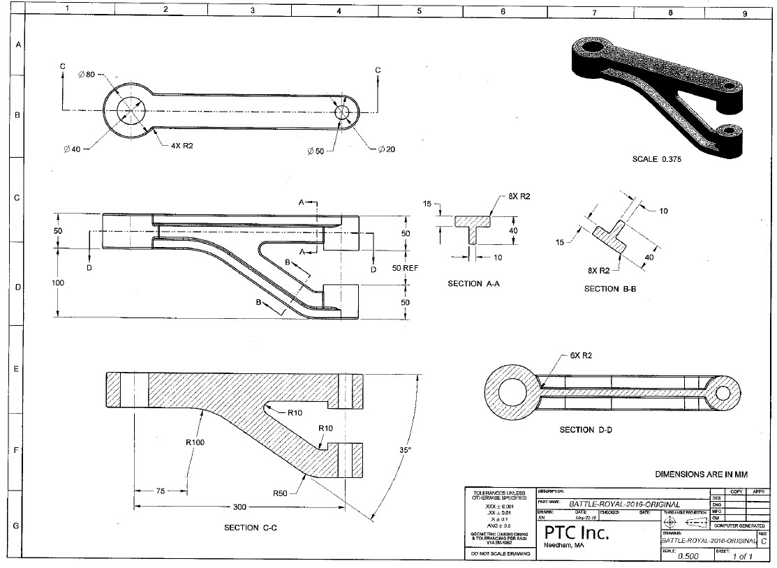
Good day everyone,
Amit Deshpande and I have returned from LiveWorx; it was excellent to say hello to community members in person.
One of the most popular stops on the expo floor was this Creo "race." How about some friendly competition for bragging rights?
Please give this part a try and let us know how long it took you to draw it. Feel free to set up some video with a timer 
Best,
Toby
This thread is inactive and closed by the PTC Community Management Team. If you would like to provide a reply and re-open this thread, please notify the moderator and reference the thread. You may also use "Start a topic" button to ask a new question. Please be sure to include what version of the PTC product you are using so another community member knowledgeable about your version may be able to assist.
Labels:
- Labels:
-
General
19 REPLIES 19
Jun 09, 2016
11:37 PM
- Mark as New
- Bookmark
- Subscribe
- Mute
- Subscribe to RSS Feed
- Permalink
- Notify Moderator
Please log in to access translation
Jun 09, 2016
11:37 PM
It took about 20 minutes. I had to redo the radii a couple of ways because the radius solver seems to try to solve multiple radii sets simultaneously (Set1, Set2, Set3) as opposed to sequentially, so I ended up creating multiple round features. I don't do a lot of rounds, so maybe I've missed a shortcut.
The part is double-dimensioned where the R10 on the lower boss is. This is covered by the R50 and the assumption that the 40 dim for the depth of the web in section B-B applies through the entire lower branch.
A more interesting challenge would be to give a drawing, an amount of time to build a compliant model, then give a new drawing that is roughly based on the first to see how flexible the original model was and how adaptations need to be made to get there.
I've seen this in practice and the results aren't pretty.
Jun 10, 2016
06:21 AM
- Mark as New
- Bookmark
- Subscribe
- Mute
- Subscribe to RSS Feed
- Permalink
- Notify Moderator
Please log in to access translation
Jun 10, 2016
06:21 AM
David Schenken wrote:
A more interesting challenge would be to give a drawing, an amount of time to build a compliant model, then give a new drawing that is roughly based on the first to see how flexible the original model was and how adaptations need to be made to get there.
I completely agree! Better yet, give your first model to a colleague who then has to make the required changes, and take the total time...
Toby, before I start on this, do you have a job code that I can book to on my timesheet? 
Jun 10, 2016
10:10 AM
- Mark as New
- Bookmark
- Subscribe
- Mute
- Subscribe to RSS Feed
- Permalink
- Notify Moderator
Please log in to access translation
Jun 10, 2016
10:10 AM
David Schenken wrote:
A more interesting challenge would be to give a drawing, an amount of time to build a compliant model, then give a new drawing that is roughly based on the first to see how flexible the original model was and how adaptations need to be made to get there.
I've seen this in practice and the results aren't pretty.
Absolutely. I don't care as much about how fast you do the first iteration, far more important is how quickly I can iterate as the design spec evolves.
I remember a challenge like this at the last PTCUser conference I attended (probably 8 years ago). I failed spectacularly (I was several multiples of the fastest time and the average, I believe) because I was staring at the drawing trying to decide how I would best model it to capture the communicated design intent directly so that it could be quickly iterated later. That contest included not only the modeling time but the time you spent reviewing the drawing. The handed you the drawing and started the clock.
If I end up with some open time next week, I'll give this a shot.
Jun 11, 2016
12:16 AM
- Mark as New
- Bookmark
- Subscribe
- Mute
- Subscribe to RSS Feed
- Permalink
- Notify Moderator
Please log in to access translation
Jun 11, 2016
12:16 AM
OK - so I cracked the round problem by going for Round All. Which explains why all the rounds on the drawing were 2mm. Round All demos well, but I've never cared to put radii on external edges; would rather put chamfers there. I guess it would be different for molded parts, except the parting line. The chamfers are because I don't like mismatch when a round-over tool is used.
Jun 13, 2016
04:17 PM
- Mark as New
- Bookmark
- Subscribe
- Mute
- Subscribe to RSS Feed
- Permalink
- Notify Moderator
Please log in to access translation
Jun 13, 2016
04:17 PM
The part is double-dimensioned where the R10 on the lower boss is. This is covered by the R50 and the assumption that the 40 dim for the depth of the web in section B-B applies through the entire lower branch.
On an injection molded part, the R10 dimension is not a double-dimension as you cannot assume that the R50 with the 40 material width carries through to the blend. That blend could be any value from 0 to R30 depending on how much flat was wanted between the boss and the inner surface.
Leaving the R10 dimension off the drawing leads to assumptions, while placing it adds to the part definition clarification.
Jun 13, 2016
04:47 PM
- Mark as New
- Bookmark
- Subscribe
- Mute
- Subscribe to RSS Feed
- Permalink
- Notify Moderator
Please log in to access translation
Jun 13, 2016
04:47 PM
I'd say that it's under dimensioned regardless of the manufacturing process. 
There's nothing to indicate how wide the T-section is where it meets the boss, the red line here:
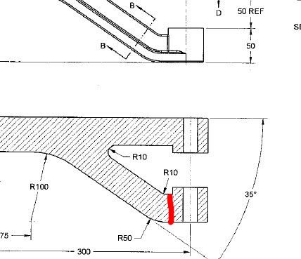
It's 40mm if we assume that the R50 & the R10 and concentric, but there is no reason they have to be. The width at the red line could be more or less than 40mm, limited only by the other geometry. Obviously, since the boss is 50mm, it can't be 50mm or greater and there is a lower limit where the the R10 starts to intersect the boss and the horizontal line disappears.
40mm is a reasonable, but not necessary, assumption.
Also, there doesn't seem to be anything that locates the 10mm thick middle rib shown in sections A-A and B-B. I'd assume that it's in the center of the part, but absent a centerline or dimension, there's no way to say for sure.
Jun 24, 2016
09:41 AM
- Mark as New
- Bookmark
- Subscribe
- Mute
- Subscribe to RSS Feed
- Permalink
- Notify Moderator
Please log in to access translation
Jun 24, 2016
09:41 AM
The four best ones were asked to compete again, with a revised drawing. They had to open their original models, and had to change the angle of the right two bosses. So design intent on buildup was important! Not sure who won.
Jun 24, 2016
03:42 PM
- Mark as New
- Bookmark
- Subscribe
- Mute
- Subscribe to RSS Feed
- Permalink
- Notify Moderator
Please log in to access translation
Jun 24, 2016
03:42 PM
But it had to be one of the first (4) fastest in order to even be considered for the updates.
Jun 24, 2016
03:46 PM
- Mark as New
- Bookmark
- Subscribe
- Mute
- Subscribe to RSS Feed
- Permalink
- Notify Moderator
Please log in to access translation
Jun 24, 2016
03:46 PM
The changes were actually relatively easy...IF you had a good understanding of flexible modeling. Unfortunately, none of the 4 were able to make the changes exactly as specified, so the winner ended up being the one who got the closest. I have a copy of the 2nd round drawing here somewhere if anyone is interested...
Jun 24, 2016
04:05 PM
- Mark as New
- Bookmark
- Subscribe
- Mute
- Subscribe to RSS Feed
- Permalink
- Notify Moderator
Please log in to access translation
Jun 24, 2016
04:05 PM
Tom Uminn wrote:
... Unfortunately, none of the 4 were able to make the changes exactly as specified, so the winner ended up being the one who got the closest. ...
Close enough typically works well for our clients too. 
Jun 30, 2016
11:49 AM
- Mark as New
- Bookmark
- Subscribe
- Mute
- Subscribe to RSS Feed
- Permalink
- Notify Moderator
Please log in to access translation
Jun 30, 2016
11:49 AM
I just took another look and I can only find the original. Apparently it didn't make it home from Boston. 
Toby Metcalf, any chance you can get a copy? (Ask Raphael N., I'm pretty sure he drew it.)
Jun 30, 2016
01:40 PM
- Mark as New
- Bookmark
- Subscribe
- Mute
- Subscribe to RSS Feed
- Permalink
- Notify Moderator
Please log in to access translation
Jun 30, 2016
01:40 PM
I will look into it
Jun 24, 2016
10:05 AM
- Mark as New
- Bookmark
- Subscribe
- Mute
- Subscribe to RSS Feed
- Permalink
- Notify Moderator
Please log in to access translation
Jun 24, 2016
10:05 AM
Greetings all -
Would you like a quarterly challenge like this? I would be willing to consider some type of prize for the winner.
Cheers,
Toby
Jun 28, 2016
05:24 PM
- Mark as New
- Bookmark
- Subscribe
- Mute
- Subscribe to RSS Feed
- Permalink
- Notify Moderator
Please log in to access translation
Jun 28, 2016
05:24 PM
Random 2 cents here. Just to echo what was said above, a speed challenge, isn't much of a challenge. Robustness of the model would be more challenging (and educational), but that can also be partly subjective.
I would say go back to the Nest smoke detector thread a couple years ago where we were figuring out the hole pattern. Those are the kind of challenges I prefer.
edit: this
Nest smoke alarm: How to create the "fibonacci-like" hole-pattern
Jun 28, 2016
05:53 PM
- Mark as New
- Bookmark
- Subscribe
- Mute
- Subscribe to RSS Feed
- Permalink
- Notify Moderator
Please log in to access translation
Jun 28, 2016
05:53 PM
I would agree with that perspective. Also maybe add challenges regarding processes that could reveal some less that obvious solutions.
Us stand-alone people still have challenges with things like revisions, duplication, and other things that PTC has put hard earned development into that get very little recognition, and thereby, very little use by users. Maybe they are there to help other developed routines but if the user never learned about them, it is a waste of good tech.
Jun 29, 2016
08:27 AM
- Mark as New
- Bookmark
- Subscribe
- Mute
- Subscribe to RSS Feed
- Permalink
- Notify Moderator
Please log in to access translation
Jun 29, 2016
08:27 AM
Thanks for the feedback guys!
I agree regarding accuracy over speed: not only would it be very hard for me to monitor (unless each person wanted to video themselves ), but it does not how fast you do it if you are doing it wrong. I will give this consideration and report.
Best,
Toby
Jun 29, 2016
03:14 PM
- Mark as New
- Bookmark
- Subscribe
- Mute
- Subscribe to RSS Feed
- Permalink
- Notify Moderator
Please log in to access translation
Jun 29, 2016
03:14 PM
I am sure no one in this group would ever try to pull something over on me Steven 
Jun 29, 2016
08:54 PM
- Mark as New
- Bookmark
- Subscribe
- Mute
- Subscribe to RSS Feed
- Permalink
- Notify Moderator
Please log in to access translation
Jun 29, 2016
08:54 PM
That's why I would use AutoIt instead of a trail file or mapkeys. It makes the mouse pointer move so Camtasia can see it. The end product is much more convincing.
Jul 22, 2016
12:30 PM
- Mark as New
- Bookmark
- Subscribe
- Mute
- Subscribe to RSS Feed
- Permalink
- Notify Moderator
Please log in to access translation
Jul 22, 2016
12:30 PM
Thanks everyone for your comments.
I think this will be a fun idea, now I just need to do some planning.
Best,
Toby


