Community Tip - New to the community? Learn how to post a question and get help from PTC and industry experts! X
- Community
- Creo+ and Creo Parametric
- 3D Part & Assembly Design
- Re: About making draft lines
- Subscribe to RSS Feed
- Mark Topic as New
- Mark Topic as Read
- Float this Topic for Current User
- Bookmark
- Subscribe
- Mute
- Printer Friendly Page
About making draft lines
- Mark as New
- Bookmark
- Subscribe
- Mute
- Subscribe to RSS Feed
- Permalink
- Notify Moderator
About making draft lines
If you don't have mold options,
do you know way of making draft lines by standard feature ?
Please tell me the way if you have ideas.
This thread is inactive and closed by the PTC Community Management Team. If you would like to provide a reply and re-open this thread, please notify the moderator and reference the thread. You may also use "Start a topic" button to ask a new question. Please be sure to include what version of the PTC product you are using so another community member knowledgeable about your version may be able to assist.
Solved! Go to Solution.
Accepted Solutions
- Mark as New
- Bookmark
- Subscribe
- Mute
- Subscribe to RSS Feed
- Permalink
- Notify Moderator
And one more that uses the tangent surface feature. Not completely intuitive and a difficult to manage interface, but the angle should be a consistent 15 degrees.
As with all things that require draft angles, this really puts you in what I term "a 12D environment". There are so many ways to define the same (similar) thing that it is hard to second guess the designer or the toolmaker.
In this instance, I had to go to the help pages to get some guidance on the Tangent Surface module. Even so, it was tricky to get even the basic version to work.
Since the top is sloped, the 175mm offset surface is there to make sure the tangency angle is maintained. A section defined the offset required for the 15 degree tangency.
- Mark as New
- Bookmark
- Subscribe
- Mute
- Subscribe to RSS Feed
- Permalink
- Notify Moderator
Do you mean parting lines?
- Mark as New
- Bookmark
- Subscribe
- Mute
- Subscribe to RSS Feed
- Permalink
- Notify Moderator
Yes ! parting line.
- Mark as New
- Bookmark
- Subscribe
- Mute
- Subscribe to RSS Feed
- Permalink
- Notify Moderator
You just have model everything that I know of. I did it for a few months, it's slow depending on the part.
- Mark as New
- Bookmark
- Subscribe
- Mute
- Subscribe to RSS Feed
- Permalink
- Notify Moderator

↑
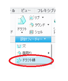
That is parting line icon.
Thanks for your message.
Yes I understand it's slow depending on the part.
I want to know the way even if slow.
- Mark as New
- Bookmark
- Subscribe
- Mute
- Subscribe to RSS Feed
- Permalink
- Notify Moderator
Like I said, just have to model it with standard tools.
Again, not knowing the part, but you can start by drawing a cavity block and a core block, assemble the blocks and the part in the correct orientation. Then you scale the part (when shrinkage tool not available). Then you can activate one of the blocks, copy all the part surfaces, and then Solidify. Do the same for the other block. Then you have a basic core and cavity to start with.
- Mark as New
- Bookmark
- Subscribe
- Mute
- Subscribe to RSS Feed
- Permalink
- Notify Moderator
OK. I see.
Thank you so much.
- Mark as New
- Bookmark
- Subscribe
- Mute
- Subscribe to RSS Feed
- Permalink
- Notify Moderator
I've never seen that icon before. Are you using Creo 3?
There are many ways to create and control parting lines using basic Creo Parametric. Essentially, parting line = draft hinge. In the standard Draft and the Variable Pull Direction Draft tools you can make the draft hinge be surfaces, edges, datum planes, and sketched curves. Hinging off of a sketched curve is a really powerful capability. Combine that with the Variable Pull Direction Draft and you can get some pretty wild drafted surfaces/parting lines.

- Mark as New
- Bookmark
- Subscribe
- Mute
- Subscribe to RSS Feed
- Permalink
- Notify Moderator
If I recall correctly, there was a tutorial that showed using offset surfaces (offset by 0) to create the two mold halves. This would effectively give you an edge to develop mold tools from.
- Mark as New
- Bookmark
- Subscribe
- Mute
- Subscribe to RSS Feed
- Permalink
- Notify Moderator
I use Creo 2.
Thank you for your message.
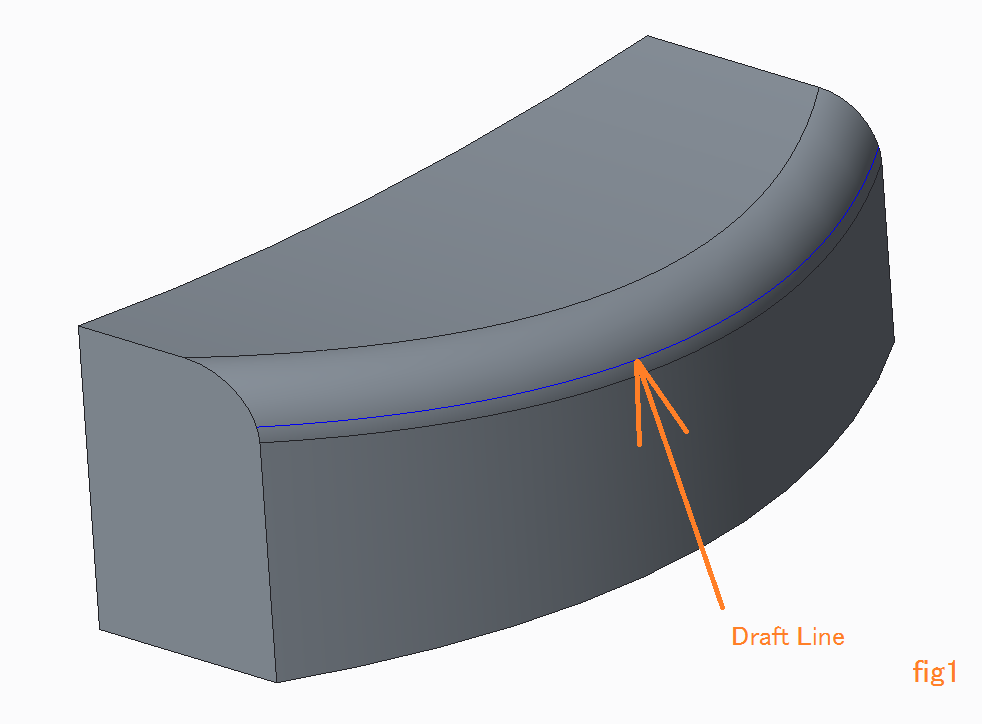
I want to make draft lines for shape of fig1.

If you make draft surfaces that is tangent to the round surface,
it is very easy to make it by draft lines.
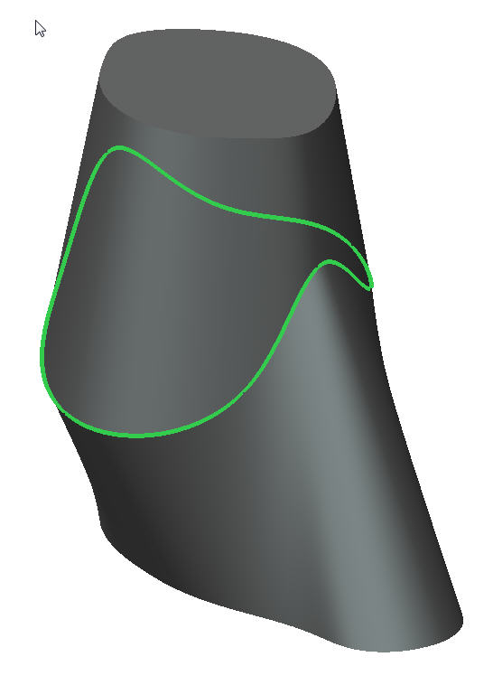
Now I can find position of draft lines to use draft analysis like fig2 .
But I don't know way of making draft lines without mold option.
- Mark as New
- Bookmark
- Subscribe
- Mute
- Subscribe to RSS Feed
- Permalink
- Notify Moderator
You part appear to have zero draft with the exception of the curved surface. According to the analysis, the draft line is at 15 degrees of the round feature. You could do this with a sweep where the sweep would could be a surface with the edge at the desired location.
The way you have this post defined, you would have an undercut if you placed the parting line as you show in the second image. Maybe we are not understanding your goal?
- Mark as New
- Bookmark
- Subscribe
- Mute
- Subscribe to RSS Feed
- Permalink
- Notify Moderator
My goal is very simple.
I want to know other way to make draft lines without mold option.
I want to know way to make it with standerd features.
I will give up if we can't make it without mold option.
- Mark as New
- Bookmark
- Subscribe
- Mute
- Subscribe to RSS Feed
- Permalink
- Notify Moderator
What Antonius said. If you split it there, it is undercut, because the front wall is straight.
There must be a different part you are working on that is slightly different?
Like if that straight wall is drafted in, then the radius has to be split, is that what you want?
- Mark as New
- Bookmark
- Subscribe
- Mute
- Subscribe to RSS Feed
- Permalink
- Notify Moderator
The easiest way to make that line is to draft the wall before adding the round feature.
To do it after the fact, you would use a sweep feature with the 15 degrees locked in the sketch.
- Mark as New
- Bookmark
- Subscribe
- Mute
- Subscribe to RSS Feed
- Permalink
- Notify Moderator
- Mark as New
- Bookmark
- Subscribe
- Mute
- Subscribe to RSS Feed
- Permalink
- Notify Moderator
- Mark as New
- Bookmark
- Subscribe
- Mute
- Subscribe to RSS Feed
- Permalink
- Notify Moderator
- Mark as New
- Bookmark
- Subscribe
- Mute
- Subscribe to RSS Feed
- Permalink
- Notify Moderator
Thanks.
I think that sweep is good way.
But I don't understand how to create that shape.
I tried, but my sweep edge's line isn't same (=draft lines).
Please give me creo's data.
- Mark as New
- Bookmark
- Subscribe
- Mute
- Subscribe to RSS Feed
- Permalink
- Notify Moderator
I did not save the change. I will recreate it later today.
- Mark as New
- Bookmark
- Subscribe
- Mute
- Subscribe to RSS Feed
- Permalink
- Notify Moderator
I have created 3 versions using the sweep technique. Each more preferable then the previous depending on the level of effort required.
1st is a simple sweep that follows the exiting edges of the round. This creates a few artifacts that may or may not be acceptable. In general, they would disappear in tooling.
2nd is the preferred version where the round's edges are extended for the sweep feature.
3rd reconstructs the round geometry and replaces the 50mm normal round with a C2 round feature.
This is the location where the 15 degree line is established
- Mark as New
- Bookmark
- Subscribe
- Mute
- Subscribe to RSS Feed
- Permalink
- Notify Moderator
And one more that uses the tangent surface feature. Not completely intuitive and a difficult to manage interface, but the angle should be a consistent 15 degrees.
As with all things that require draft angles, this really puts you in what I term "a 12D environment". There are so many ways to define the same (similar) thing that it is hard to second guess the designer or the toolmaker.
In this instance, I had to go to the help pages to get some guidance on the Tangent Surface module. Even so, it was tricky to get even the basic version to work.
Since the top is sloped, the 175mm offset surface is there to make sure the tangency angle is maintained. A section defined the offset required for the 15 degree tangency.
- Mark as New
- Bookmark
- Subscribe
- Mute
- Subscribe to RSS Feed
- Permalink
- Notify Moderator
Thank you so much.
These answers were helped me and my problems was closed.![]()
- Mark as New
- Bookmark
- Subscribe
- Mute
- Subscribe to RSS Feed
- Permalink
- Notify Moderator
please upload a step file...
- Mark as New
- Bookmark
- Subscribe
- Mute
- Subscribe to RSS Feed
- Permalink
- Notify Moderator
- Mark as New
- Bookmark
- Subscribe
- Mute
- Subscribe to RSS Feed
- Permalink
- Notify Moderator
i have derived rough mold plates..please check it..and do open the assembly first.
- Mark as New
- Bookmark
- Subscribe
- Mute
- Subscribe to RSS Feed
- Permalink
- Notify Moderator
Thank you so much .


