Community Tip - Need to share some code when posting a question or reply? Make sure to use the "Insert code sample" menu option. Learn more! X
- Community
- Creo+ and Creo Parametric
- 3D Part & Assembly Design
- Re: Accuracy Question
- Subscribe to RSS Feed
- Mark Topic as New
- Mark Topic as Read
- Float this Topic for Current User
- Bookmark
- Subscribe
- Mute
- Printer Friendly Page
Accuracy Question
- Mark as New
- Bookmark
- Subscribe
- Mute
- Subscribe to RSS Feed
- Permalink
- Notify Moderator
Accuracy Question
How does Creo (using Creo Parametric 3) handle accuracy. It confuses me that there is a relative accuracy and an absolute accuracy. And that relative accuracy seems to be the default.
Also having some issues with imported parts. Our workflow is this:
- Part designed in Catia (Catia global tolerance set to 0.001mm) and saved as CATpart.
- Part imported into Creo for mould/jig design but Creo states that accuracy is now 0.05mm. Setting the accuracy finer (back to 0.001mm) results in part being converted from a solid to a surface due to (usually very many) naked edges. File needs to be extensively repaired to continue work in Creo or work is continued at 0.05mm accuracy.
Why is a part accuracy changed. How does the change in accuracy impact the design as a whole?
Thanks
This thread is inactive and closed by the PTC Community Management Team. If you would like to provide a reply and re-open this thread, please notify the moderator and reference the thread. You may also use "Start a topic" button to ask a new question. Please be sure to include what version of the PTC product you are using so another community member knowledgeable about your version may be able to assist.
- Labels:
-
Sheet Metal Design
- Mark as New
- Bookmark
- Subscribe
- Mute
- Subscribe to RSS Feed
- Permalink
- Notify Moderator
- Mark as New
- Bookmark
- Subscribe
- Mute
- Subscribe to RSS Feed
- Permalink
- Notify Moderator
Thanks. It confirms what I had suspected in terms of AA vs RA
BUT
It doesn't explain the constant issues we have with Catia/step/iges files.
Also its worth pointing out that the thread in your link is 7 years old and the link mentioned in the thread is already 9 years old. Any changes to this?
- Mark as New
- Bookmark
- Subscribe
- Mute
- Subscribe to RSS Feed
- Permalink
- Notify Moderator
in all honesty, I did a search using "absolute vs relative" and I got a host of hits.
I open one that seemed to address your question regarding accuracy.
Regarding importing, try this thread
Is there a way to define accuracy for STEP export?
ron
- Mark as New
- Bookmark
- Subscribe
- Mute
- Subscribe to RSS Feed
- Permalink
- Notify Moderator
There are plenty of hits, none which answer my question. Particular the import issue.
- Mark as New
- Bookmark
- Subscribe
- Mute
- Subscribe to RSS Feed
- Permalink
- Notify Moderator
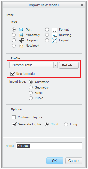
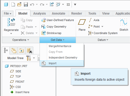
When importing a file, Creo will attempt to use a "template" part (or assembly). This template model will already have the accuracy pre-defined, so that is the accuracy the imported model will be held to. If you instead tell Creo to not use a template, you will get the equivalent of a new, empty part with the accuracy set to relative.


Keep in mind that you can always create the Creo model first, set the accuracy to whatever you want, and then import the dumb file into this model. The imported geometry will be held to whatever accuracy the model already is at.

- Mark as New
- Bookmark
- Subscribe
- Mute
- Subscribe to RSS Feed
- Permalink
- Notify Moderator
Thanks Tom for providing the "picture is worth a thousand words" explanation.
- Mark as New
- Bookmark
- Subscribe
- Mute
- Subscribe to RSS Feed
- Permalink
- Notify Moderator
Tom: This is kind of funny because I got help from PTC support on this type of issue this week.
It drove us nuts that we have our tolerance set to absolute .0005 inches for our part and assembly start parts and every time we would bring in a customer STEP model it would change the model to Relative .0012.
It was pointed out to us that we needed to do as you've shown, but also set a couple config options.
1. Add the config option template_designasm
2. Add the config option template_solidpart
- Mark as New
- Bookmark
- Subscribe
- Mute
- Subscribe to RSS Feed
- Permalink
- Notify Moderator
Sebastian Finke wrote:
... Also its worth pointing out that the thread in your link is 7 years old and the link mentioned in the thread is already 9 years old. Any changes to this?
Funny, I saw this email notice and came to post some info only to find someone already posted a link to me talking about it 7 years ago. ![]()
I've been using Creo & Proe since 1996 and this has been pretty much the same the entire time.
Set the accuracy you want in your "start part" or template and tell Creo to use your template when importing.
- Mark as New
- Bookmark
- Subscribe
- Mute
- Subscribe to RSS Feed
- Permalink
- Notify Moderator
Importing files, defining accuracy settings, and setting defaults have a bunch of configuration options too. You may want to look into the config files to see what options you want to set.
Chances are that you can change a few settings that will affect the way your accuracy / import works and you won't have to worry about it much after that...
- Mark as New
- Bookmark
- Subscribe
- Mute
- Subscribe to RSS Feed
- Permalink
- Notify Moderator
Ok it seems the problem may lie with the imported part.
Our Creo template has accuracy set to 0.0005mm. The imported file (created in Catia) will not solidify at anything under 0.01mm. My fix for this is to have the Catia join tolerance increased from the default 0.001mm to, say, 0.05mm and see if that works.
- Mark as New
- Bookmark
- Subscribe
- Mute
- Subscribe to RSS Feed
- Permalink
- Notify Moderator
That's a very small accuracy default (I assume that you are using absolute). We use 0.0001" in our English templates and 0.00254mm in our metric.
- Mark as New
- Bookmark
- Subscribe
- Mute
- Subscribe to RSS Feed
- Permalink
- Notify Moderator
We use very similar values as well.
I don't think you want to go much smaller than is necessary, just adds more calculations and complexity.
- Mark as New
- Bookmark
- Subscribe
- Mute
- Subscribe to RSS Feed
- Permalink
- Notify Moderator
Fair enough but I have tried 0.001 and 0.005 too (all absolute) and that wouldn't import either. It had to be 0.01 or larger.
I also believe that so-called 'realistic' tolerances are for the shop floor, not the design office. If software (regardless of whether it is Catia or Creo) joins a surface but sais surface still has gaps of over 0.01mm then that's a huge flaw in my eyes.


