
Turn on suggestions
Auto-suggest helps you quickly narrow down your search results by suggesting possible matches as you type.
Showing results for
Please log in to access translation
Turn on suggestions
Auto-suggest helps you quickly narrow down your search results by suggesting possible matches as you type.
Showing results for
Community Tip - Stay updated on what is happening on the PTC Community by subscribing to PTC Community Announcements. X
- Community
- Creo+ and Creo Parametric
- 3D Part & Assembly Design
- Actual tolerance different than default tolerance
Translate the entire conversation x
Please log in to access translation
Options
- Subscribe to RSS Feed
- Mark Topic as New
- Mark Topic as Read
- Float this Topic for Current User
- Bookmark
- Subscribe
- Mute
- Printer Friendly Page
Actual tolerance different than default tolerance
Aug 26, 2016
03:15 PM
- Mark as New
- Bookmark
- Subscribe
- Mute
- Subscribe to RSS Feed
- Permalink
- Notify Moderator
Please log in to access translation
Aug 26, 2016
03:15 PM
Actual tolerance different than default tolerance
I swear I've seen a solution to this before, but I can't seem to find it with the PTC site changes.
Using Creo 3, but have had this problem on Creo 2 and Wildfire 5. I know it worked differently in Wildfire 4 and before, but we don't need to talk about things that worked right in old versions, were changed / "improved", and now suck.
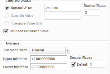
The start part has the default 3-place tolerance set as +/- .005. If the default_dec_places is 3, the tolerance of new features is +/- 0.0049999999
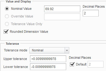
The start part has the default 2-place tolerance set as +/- .01. If the default_dec_places is 2, the tolerance of new features is +/- 0.00999999978.
Besides being annoying, it's wrong. How do I fix the start part?

This thread is inactive and closed by the PTC Community Management Team. If you would like to provide a reply and re-open this thread, please notify the moderator and reference the thread. You may also use "Start a topic" button to ask a new question. Please be sure to include what version of the PTC product you are using so another community member knowledgeable about your version may be able to assist.
Labels:
- Labels:
-
Sheet Metal Design
5 REPLIES 5
Aug 26, 2016
03:44 PM
- Mark as New
- Bookmark
- Subscribe
- Mute
- Subscribe to RSS Feed
- Permalink
- Notify Moderator
Please log in to access translation
Aug 26, 2016
03:44 PM
You have more than I do. In Creo 3 M020, I have the parameters set in config.pro, but Creo just ignores it.
However, it does maintain a nice rounded number without issue in the dimension properties dialog.
Aug 26, 2016
09:22 PM
- Mark as New
- Bookmark
- Subscribe
- Mute
- Subscribe to RSS Feed
- Permalink
- Notify Moderator
Please log in to access translation
Aug 26, 2016
09:22 PM
Are you totally sure your start part has the tolerances shown in the inset? Maybe someone changed the start part. One scenario comes to mind - units were changed, part regenerated, then units were changed back and part was regenerated again and saved. Well, I think that after that, the tolerance values will be scrambled up, even though they seem to show up fine in the graphics area. I'm not saying this is what happened in your case, but I played around with my Creo 2, M210 and discovered this bug: try if same thing happens to you:
Use your troubled start part to make a new model.
Switch to Annotate tab. Now you can double click on the values next to the X.X , X.XX etc..
Double click on the X.XX (linear_tol_0_00) the input box should say 0.01 - but type it in again - really, just write in 0.01.
Do the same for X.XXX (linear_tol_0_000) - probably showing 0.005 - don't believe it - type in 0.005.
Now try to make a new dimensions. Your newly placed dimensions should show up with the correct tolerance (+/- 0.01 if default_dec_places was 2, +/- 0.005 if default_dec_places was 3).
So now, do this:
Switch to Annotate tab; double click on 0.01; this time, type in 0.0096.
The display should show X.XX +/- 0.01.
Double click on the 0.01 again. The input box will show 0.01. Just press enter to accept this.
You'd think that would be changing linear_tol_0_00 to be 0.01; not so:
Make default_dec_places 2 in the configuration editor.
Create a new dimension. Is its tolerance value +/- 0.0096 ?
If so, it just confirms that this software needs more testing, bug reports and their resolutions.
Aug 26, 2016
10:33 PM
- Mark as New
- Bookmark
- Subscribe
- Mute
- Subscribe to RSS Feed
- Permalink
- Notify Moderator
Please log in to access translation
Aug 26, 2016
10:33 PM
Those look like the software is not rounding the display of those numbers. Floating point numbers are base 2, which rarely (never?) matches base 10.
Not sure why it's working this way for you and not everyone else, but you may have to turn the part over to PTC for them to see the structure. Doesn't even need features in it. Probably some rounding setting that isn't controllable by the user anyway.
(for too much to read look for What Every Computer Scientist Should Know About Floating-Point Arithmetic
It's in a lot of places, like https://docs.oracle.com/cd/E19957-01/806-3568/ncg_goldberg.html)
Aug 31, 2016
02:35 PM
- Mark as New
- Bookmark
- Subscribe
- Mute
- Subscribe to RSS Feed
- Permalink
- Notify Moderator
Please log in to access translation
Aug 31, 2016
02:35 PM
As a side note to the response about modifying the values from the tags on the screen in Annotate tab:
If you are unable to use that mechanism, because you want a default tol that isn't the tags (for example, the default tolerance for linear dimensions with 4 decimal places, or for angular dimensions with 2 decimal places), then you can change it with another (more cumbersome workflow):
In the Annotate tab, make a note, and put &linear_tol_0_0000 (for example, for the 4-dec-place linear dimension tolerance) as the text. This will become a callout of the desired default tolerance from the prat. Then you can Edit Value on this callout to change it (and delete the note afterward).
If you want to do something further, such as the number of digits of the default tolerance in an existing part (1.23 +/- 0.007 for example) you'll need to either 1) employ ProSolidToleranceSet in the Toolkit API, or 2) send the part to PTC to patch, or 3) ask PTC Product Management to implement some UI for it.
As a side note to the response about the config.pro options, please note that the config.pro option values are propagated to the solid model on creation, and new dimensions get their tolerance from the solid.
Sep 02, 2016
09:27 AM
- Mark as New
- Bookmark
- Subscribe
- Mute
- Subscribe to RSS Feed
- Permalink
- Notify Moderator
Please log in to access translation
Sep 02, 2016
09:27 AM
Found out that if I run Creo clean OOTB, the new feature tolerances are per the annotations in the part template. But restoring our customizations causes the problem again.
There are several prodevdat entries in the loadpoint config.pro - I suspect one of these may be causing the issue. I've kicked this to our internal CAD team to track down the .dat file that is injecting the issue and to resolve it with the .dat developers. I don't know how these .dat files were created or how they interact with the .prt, so I'm basically at the developers' mercy.


