Community Tip - Learn all about the Community Ranking System, a fun gamification element of the PTC Community. X
- Community
- Creo+ and Creo Parametric
- 3D Part & Assembly Design
- Re: Airfoil splines
- Subscribe to RSS Feed
- Mark Topic as New
- Mark Topic as Read
- Float this Topic for Current User
- Bookmark
- Subscribe
- Mute
- Printer Friendly Page
Airfoil splines
- Mark as New
- Bookmark
- Subscribe
- Mute
- Subscribe to RSS Feed
- Permalink
- Notify Moderator
Airfoil splines
Hi,
I'm just getting to grips with WF4 student/personal ed. To learn pro e I have started a project to model a vintage sailplane, top down, which I intend to scale down to create flying models in two different scales. Having now spent some time getting started there are three problems I need to get sorted up front
1) I can load airfoil shapes easy enough by using pts files/splines but I would like the shape to be parameterised. ie the airfoil changes with span and due to Reynolds number effects changes with scale. I am also likely to change the airfoil profile a number of times while prototyping and testing. Is there a way to have the airfoil profile parameterised in a family table or something similar?.
2) In sketcher the airfoil needs to be constrained so that the top surface is tangent to a plane normal to the sketch plane.
i.e the chord and angle of attack dimensioned, the tangent constrain would then determine vertical height so the top surface just touches the plane.
This works with circular geometry but proe does not allow a spline curve to be constrained this way, probably because it does not know that the intent is that the spline points are fixed relative to each other and scale only with chord, any suggestions?
3) I have not studied this yet but will ask anyway. What is the best way to create different versions of my model to different scales. I am modeling the surface shape of the sailplane in full size than want to create two different versions (and sets of drawings) to 1:4 and 1:6 scale. I can not just scale the whole model because things like material thickness will be standard thickness plywood in the scale models.
Many Thanks
Allan
This thread is inactive and closed by the PTC Community Management Team. If you would like to provide a reply and re-open this thread, please notify the moderator and reference the thread. You may also use "Start a topic" button to ask a new question. Please be sure to include what version of the PTC product you are using so another community member knowledgeable about your version may be able to assist.
- Labels:
-
General
- Mark as New
- Bookmark
- Subscribe
- Mute
- Subscribe to RSS Feed
- Permalink
- Notify Moderator
Allan,
In general, you can probably do everything you want to one way or another, although I'm not completely clear on all your requirements. Comments on your 3 questions:
1. You can certainly "parameterize" your model in many ways. I'm guessing that Relations might be even better than Family Tables, depending on how you are controlling your geometry. If you can generate straightforward logical and mathematical control outside of Pro, you should be able to incorporate your driving logic into Relations. What are you controlling, exactly? If you have to change the coordinates of every single point on your splines individually, things could be cumbersone, but if a change to a chord length and an angle, for example, update everything appropriately, you should have no problems.
2. By "plane normal to the sketch plane" do you mean horizontal? I'm not sure I understand what you are doing here. If you have an angle of attack defined, your angle is set, and location is probably fixed as well. Are you just trying to locate the highest point on the airfoil?
3. Probably you can do what you need with a combination of Parameters, Relations, and a bit of conditional logic if necessary. Family Tables are also a possibility.
If you give us a little more detail, we can probably help you more specifically.
Good luck to you; you're ambitious to start out with airfoil geometry. I would recommend researching the ptc knowledge base on the subject. In the past they have included airfoils in course exercises, illustrating scaling the section along the span and twisting the foil using angles in a General Blend.
David
- Mark as New
- Bookmark
- Subscribe
- Mute
- Subscribe to RSS Feed
- Permalink
- Notify Moderator
David,
In regard to constraining the airfoil spline I am indeed trying to locate the highest point on the airfoil. I set the angle of attack and want the high point of the airfoil to set the vertical location, therefore as I change angle of attack the high point will stay on the same horizontal line. It is fine with circular geometry but I can not make it work with a spline. I could post a sample but I only have the student version.
Many Thanks
Allan
- Mark as New
- Bookmark
- Subscribe
- Mute
- Subscribe to RSS Feed
- Permalink
- Notify Moderator
Allan,
OK, two separate issues, as I see it: (1) Design approach, & (2) Sketcher problem.
1. Are you sure this is the way you want to control the airfoil? If you have more than one section along the span (of varying size and attack angle), and you constrain them all with highest-point-in-the-same-plane, aren't you in danger of creating a "wavy" wing where the leading edge moves around in an uncontrolled way? In other words, don't you want to control the straightness or gentle curve of the leading edge or its center, then let the developing foil twist around that control?
2. You have come across a Sketcher limitation for sure. I have tried a few ways to trick it, unsuccessful so far. However, depending on your data, there still may be a way. Do you have any way of calculating the high point outside of Sketcher? If you do, you may be able to solve the Sketcher problem as follows. You can control tangency of a spline at its endpoint through dimensioning. Pick the spline, pick its endpoint, pick a coincident horizontol centerline, and place the dimension. Change the dimension value to 90, and you have tangency. If you can split your spline into two parts at the high point and dimension the ends of each where they meet in this manner, you may be able to force the issue. It depends on what you have for input. Meanwhile, I'll try another "trick" or two in Sketcher. BTW, is your input a curve for the entire foil section or just the top section? How many points define it?
David
- Mark as New
- Bookmark
- Subscribe
- Mute
- Subscribe to RSS Feed
- Permalink
- Notify Moderator
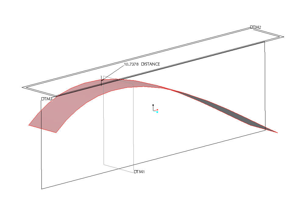
This is certainly not elegant, but is a workaround. Place your section with one dimension from the horizontal plane, making sure the section is totally below the plane, then extrude a short surface. Do a measurement from the horizontal plane to the surface (back in the 3D modeling environment), then modify the vertical dimension by subtracting the measured distance. The intersection of the surface with the vertical plane is the section you are trying to create.

- Mark as New
- Bookmark
- Subscribe
- Mute
- Subscribe to RSS Feed
- Permalink
- Notify Moderator
David,
Many thanks, this is an ok work around and better than what I come up with.
regards
Allan
- Mark as New
- Bookmark
- Subscribe
- Mute
- Subscribe to RSS Feed
- Permalink
- Notify Moderator
David,
I want to constrain the airfoil in this way because this is how it is for the full size sailplane. The points files are 133 points for the top and 133 points for the bottom but I can interpolate these easily in Matlab to any desired format/size. I think I may manually place the airfoil sections and live with having to adjust them as required. This works by duplicating the airfoil in two sketches the second references the first sketch then a line can be made tangent to the reference profile. The required distance can be manually measured to correctly place another copy of the airfoil.
thanks
Allan
- Mark as New
- Bookmark
- Subscribe
- Mute
- Subscribe to RSS Feed
- Permalink
- Notify Moderator
Glad that was helpful. On second thought, I overly complicated things by extruding the surface; you can just measure to the curve itself and move it accordingly along the lines you have just mentioned. In other words you don't really need two curves; just move the section into place after creating the temporary placement inside Sketcher.
- Mark as New
- Bookmark
- Subscribe
- Mute
- Subscribe to RSS Feed
- Permalink
- Notify Moderator
David,
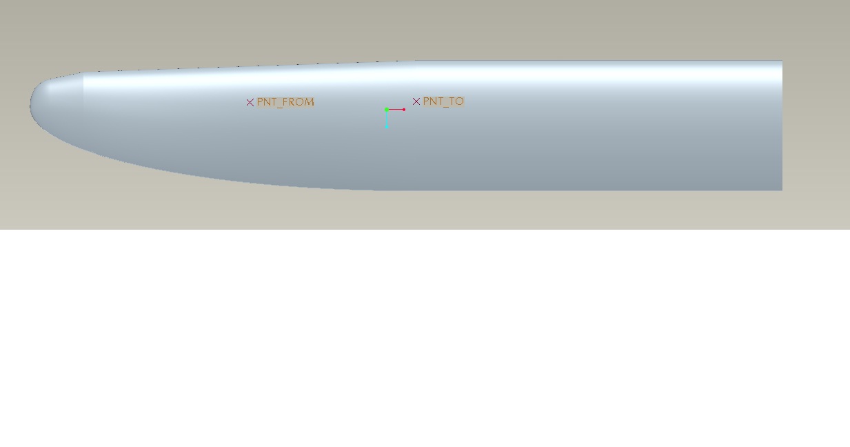
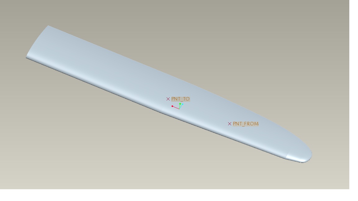
Here is the basic outline (Grunau Baby II). I ended up doing more or less as you suggested but added the analysis and optimization to the family tree so that the profiles are located automatically with each regen. The hard part now is to work out how to change profiles parametrically (all points in the airfoil spline) and add a thickened trailing edge, also parametrically driven, scale flying models have a thick trailing edge compared to the full size thing. I cant help but feel that proe does not deal with splines very efficiently.
thanks for you help
Allan


- Mark as New
- Bookmark
- Subscribe
- Mute
- Subscribe to RSS Feed
- Permalink
- Notify Moderator
Allan,
Looks good! So what kind of parametric changes do you want to make to your splines, scaling only, or something else? You are aware, I'm sure, that you can scale a saved Sketch when you bring it in to a new model. If you want to change all the numbers, however, one thing you could do is create a parameter, say "S" for scale and set its initial value to 1.00, then modify every x-y point dimension in a saved Sketch by multiplying it by S. For example,if a given dimension is 2.345 change it to 2.345*S. Now if you copy the Sketch file to a new one and change the value of S, all the x-y values will scale.
Perhaps the thickened edge could be parameterized with conditional logic. For example:
IF d39<1.6 & d39>=1.0
d54=2.00
ENDIF
etc.
David
- Mark as New
- Bookmark
- Subscribe
- Mute
- Subscribe to RSS Feed
- Permalink
- Notify Moderator
David,
My intention is to change the airfoil profile to a new shape so it is beyond just scaling a profile. I was hoping to declare the file that defines the airfoil spline as a parameter to enable the profile to be quickly changed. I can now see proe does not work that way so for know I will stick with doing it manually which is not much of a hassle. I might also look into the various API's (java) as they seem to offer a lot of possibilities.
many thanks
Allan


