
Turn on suggestions
Auto-suggest helps you quickly narrow down your search results by suggesting possible matches as you type.
Showing results for
Please log in to access translation
Turn on suggestions
Auto-suggest helps you quickly narrow down your search results by suggesting possible matches as you type.
Showing results for
Community Tip - Did you get called away in the middle of writing a post? Don't worry you can find your unfinished post later in the Drafts section of your profile page. X
- Community
- Creo+ and Creo Parametric
- 3D Part & Assembly Design
- Aligning views from different models?
Translate the entire conversation x
Please log in to access translation
Options
- Subscribe to RSS Feed
- Mark Topic as New
- Mark Topic as Read
- Float this Topic for Current User
- Bookmark
- Subscribe
- Mute
- Printer Friendly Page
Aligning views from different models?
Sep 25, 2013
09:20 AM
- Mark as New
- Bookmark
- Subscribe
- Mute
- Subscribe to RSS Feed
- Permalink
- Notify Moderator
Please log in to access translation
Sep 25, 2013
09:20 AM
Aligning views from different models?
I have a drawing that I am trying to create where I have a sub assembly that attaches to a larger assembly. For my drawing I have added both the subassembly and larger assembly to my drawing and I have created a regular view of the subassembly and a Phantom Opaque view of the larger assembly for reference. My issue now is that I need to align the two views. I seem to remember designers at a previous job doing this by aligning coordinate systems in the drawing views, but I can't seem to find a way to do this in WF4. For reference, I am using this method so that I don't create seperate "drawing models" that are unrelated to my top level master model (the drawing models have a tendency to get out of sync and are a pain to maintain). Also, I don't have write access to the top level master model so I can't use simplified reps. If anyone has advice on this issue, I would love to hear it.
This thread is inactive and closed by the PTC Community Management Team. If you would like to provide a reply and re-open this thread, please notify the moderator and reference the thread. You may also use "Start a topic" button to ask a new question. Please be sure to include what version of the PTC product you are using so another community member knowledgeable about your version may be able to assist.
Labels:
- Labels:
-
2D Drawing
4 REPLIES 4
Sep 25, 2013
11:38 AM
- Mark as New
- Bookmark
- Subscribe
- Mute
- Subscribe to RSS Feed
- Permalink
- Notify Moderator
Please log in to access translation
Sep 25, 2013
11:38 AM
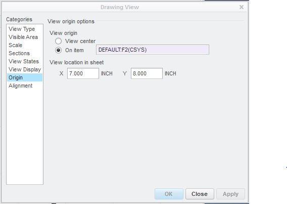
It's been a while since I've been on WF4 and I don't have access to it right now but in Creo 2.0 here's how you do it (image below)...perhaps they are similar. Also helps to turn on grid and grid snapping.
Another method would be to create a new top level assembly and assemble the top level asm and your sub asm into it. Then you have control over simplified reps, etc. and it will always update correctly so long as you assemble them the same in both top level models...perhaps via a skeleton or other universal references. Since you are completely containing the top level assembly it will always be up to date and shouldn't ever go out of sync. I've heard this technique called "working assembly" or a "master view assembly".
With this approach you might run into problems if you are doing a BOM and need balloons to point to other views that use different models. Additionally you may have to filter out the top level assembly in any BOM list.
Sep 25, 2013
11:55 AM
- Mark as New
- Bookmark
- Subscribe
- Mute
- Subscribe to RSS Feed
- Permalink
- Notify Moderator
Please log in to access translation
Sep 25, 2013
11:55 AM
neomechanikos, you got me pointed in the right direction. The option I was looking for is just below the one you have highlighted. If you go to the Alignement option, there is a way to align the views by a point or edge. Since all of my subsystems are built in relation to the main coordinate system in the top level master model, I was able to place a point at the default coordinate system in each subsystem and then use that to align the drawing views.
Sep 25, 2013
02:36 PM
- Mark as New
- Bookmark
- Subscribe
- Mute
- Subscribe to RSS Feed
- Permalink
- Notify Moderator
Please log in to access translation
Sep 25, 2013
02:36 PM
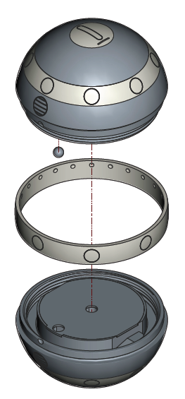
I have a similar requirement for exploded views and use the origin method. I am using shaded exploded views with extension lines and in drawings, those extension lines are not properly hidden behind solid bodies. So I create a shaded exploded view and have to align it to a no-hidden line exploded view -with- the extension lines (which hide just fine). These views don't always have the same centers due to the extension lines. I pick a feature to set the view center in each view and place it at a specific location on the drawing. As long as the feature I assign remains stable, both views remain in sync.
The problem I have with alignment is that it only aligns in vertical -or- horizontal. I can't seem to lock the views together.
There is another advantage to using the explicit coordinates for location... if you need to move one view temporarily for whatever reason, you can just change one of the coordinate locations for a time and move it back later.
Note: if the extension lines are outside the main geometry, the view's center is different than without the extension lines. Using a feature as a center will make the view center remain stable through changes making view management much simpler. From experience in a dynamic system library, locking views with a reliable and specific view center feature makes drawings much more stable. Likewise, views with alignment characteristics will remain more stable, but they normally still have one degree of freedom remaining.
Sep 25, 2013
11:57 AM
- Mark as New
- Bookmark
- Subscribe
- Mute
- Subscribe to RSS Feed
- Permalink
- Notify Moderator
Please log in to access translation
Sep 25, 2013
11:57 AM
There is the Alignment Tab too, which allows you to align one view with another.
So use the Origin tab and set the origin for the two views to their co-ordinate systems
Then Align the view horizontally and Align the views vertically
(you might be able to do both things on the alignment tab I think but not got WF4 in front of me to check)


