
Turn on suggestions
Auto-suggest helps you quickly narrow down your search results by suggesting possible matches as you type.
Showing results for
Please log in to access translation
Turn on suggestions
Auto-suggest helps you quickly narrow down your search results by suggesting possible matches as you type.
Showing results for
Community Tip - Did you get called away in the middle of writing a post? Don't worry you can find your unfinished post later in the Drafts section of your profile page. X
- Community
- Creo+ and Creo Parametric
- 3D Part & Assembly Design
- Another equation curve approximation error
Translate the entire conversation x
Please log in to access translation
Options
- Subscribe to RSS Feed
- Mark Topic as New
- Mark Topic as Read
- Float this Topic for Current User
- Bookmark
- Subscribe
- Mute
- Printer Friendly Page
Another equation curve approximation error
Jul 24, 2014
05:01 PM
- Mark as New
- Bookmark
- Subscribe
- Mute
- Subscribe to RSS Feed
- Permalink
- Notify Moderator
Please log in to access translation
Jul 24, 2014
05:01 PM
Another equation curve approximation error
I have been fighting some accuracy issues related to equation curves.
I was trying to use an even simpler version of a closed end spring when I found that for some reason, a curve from equation doesn't translate well to cylindrical sweep trajectories.
You can try this for yourself, but it really is a very distinct problem with using this particular curve type (true cosine segment).
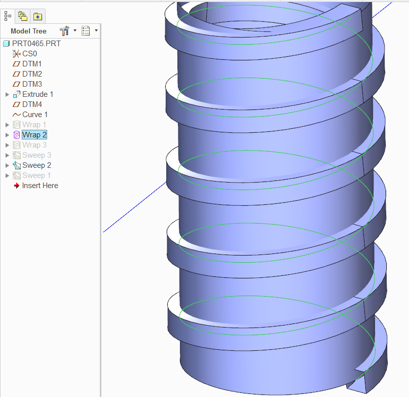
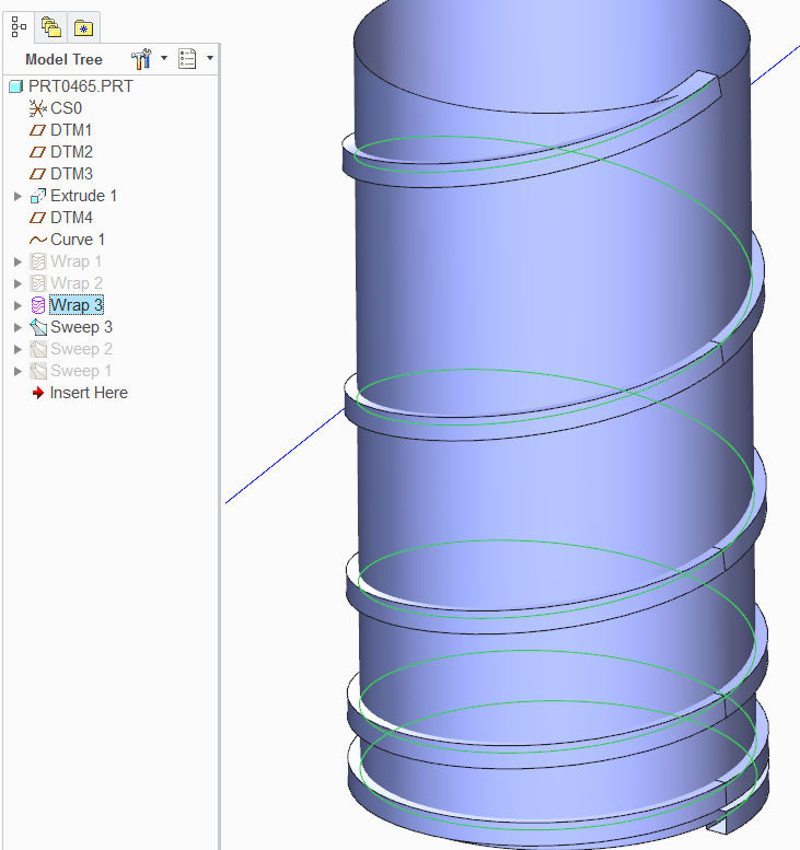
Simple part; make a wrap of an equation curve around a cylinder...
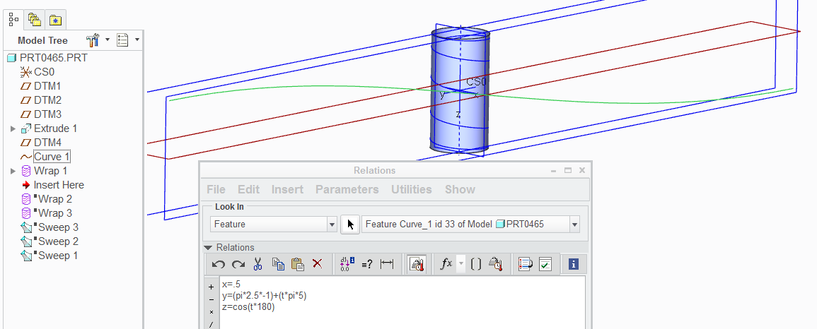
Looks nice, smooth, and properly wrapped. the wrap, of course, is a projection into the wrap-sketch of the original curve.
But, it is free of artifacts!
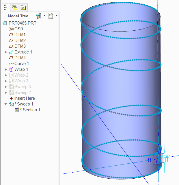
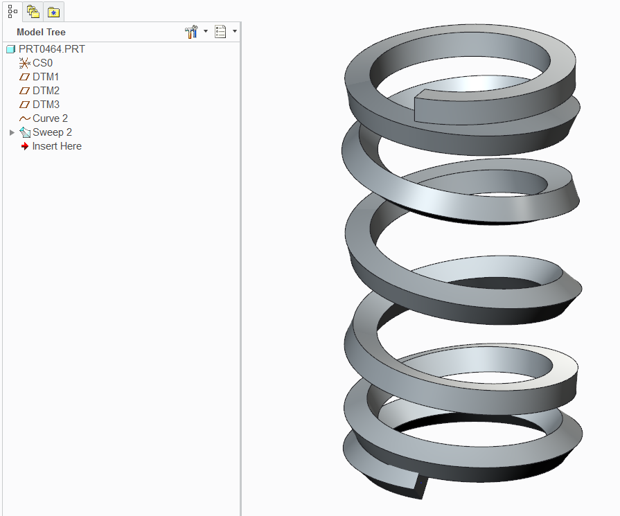
Next we sweep a sketch along its trajectory (<= this becomes important in a minute).
Notice the little blue dots along the trajectory (origin)... these are the quilt's "edges".
Close examination of the Origin shows artifacts... precision settings doesn't change this by much.
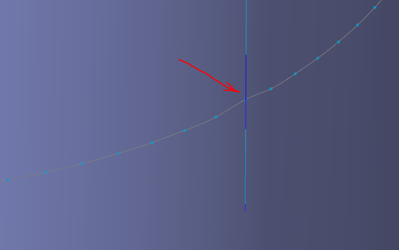
...which results in:
Now you would think this is a problem for all sweeps like this... but -NO-!
I wrapped a line and an arc along the same cylinder. No issues!
Linear:
exponential (arc)
No artifacts anywhere!
So why not create a cylindrical curve to start with?
Yea, I thought of that... 
This thread is inactive and closed by the PTC Community Management Team. If you would like to provide a reply and re-open this thread, please notify the moderator and reference the thread. You may also use "Start a topic" button to ask a new question. Please be sure to include what version of the PTC product you are using so another community member knowledgeable about your version may be able to assist.
Labels:
- Labels:
-
General
- Tags:
- cosine_curve_error
19 REPLIES 19
Jul 24, 2014
05:02 PM
- Mark as New
- Bookmark
- Subscribe
- Mute
- Subscribe to RSS Feed
- Permalink
- Notify Moderator
Please log in to access translation
Jul 24, 2014
05:02 PM
Support case submitted. Stay tuned.
I just wanted to make sure people knew about approximations happening with certain types of geometry.
Jul 24, 2014
06:40 PM
- Mark as New
- Bookmark
- Subscribe
- Mute
- Subscribe to RSS Feed
- Permalink
- Notify Moderator
Please log in to access translation
Jul 24, 2014
06:40 PM
An SPR is being filed.
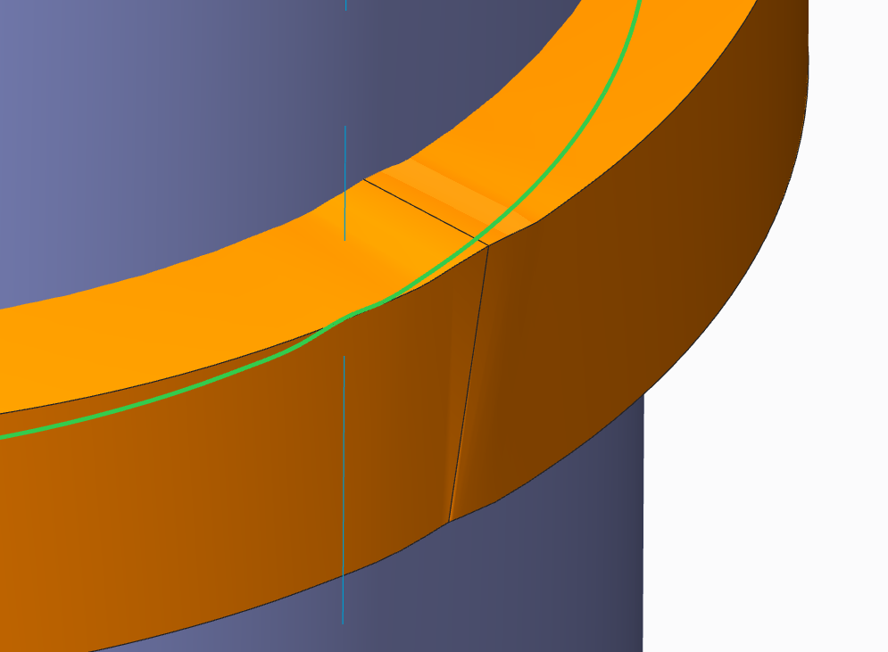
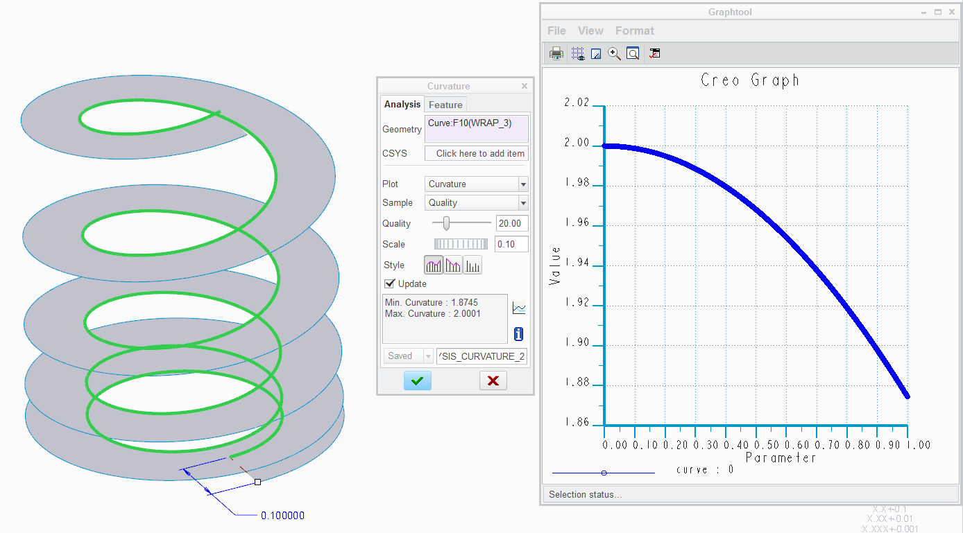
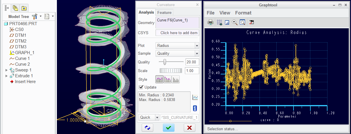
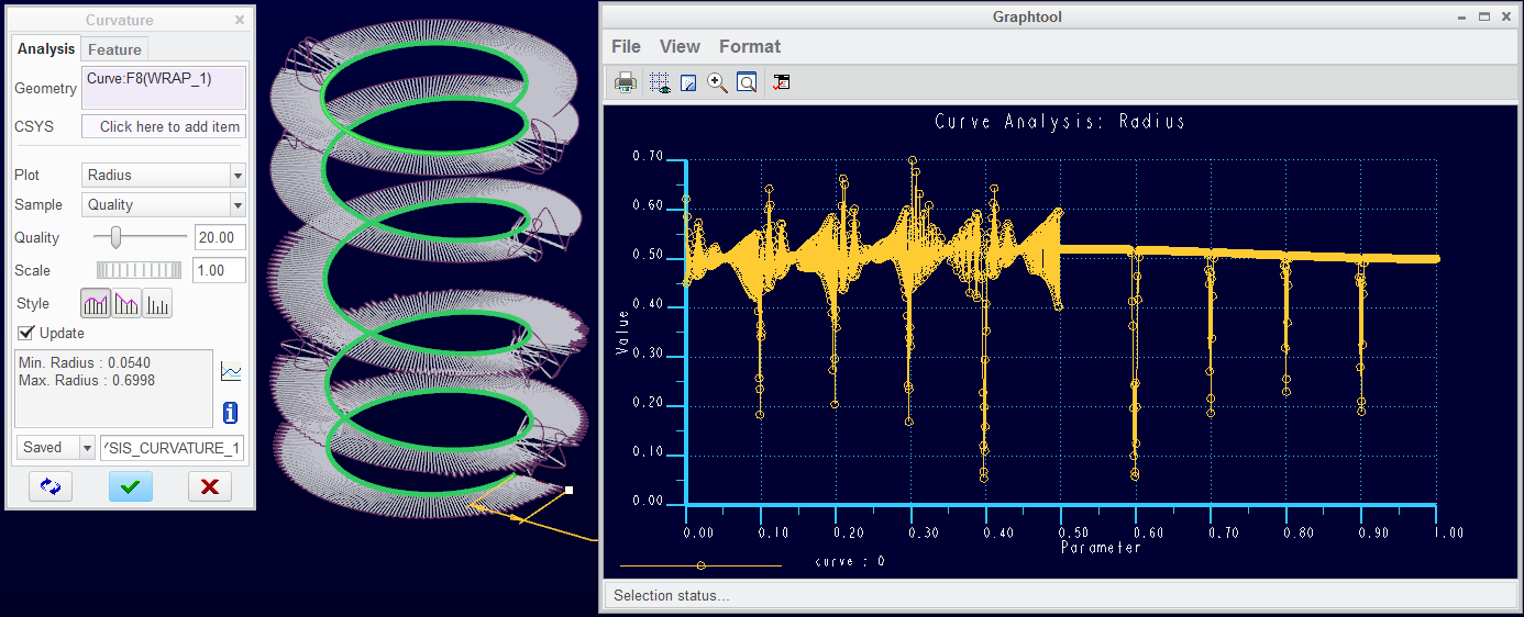
Turns out the Wrap feature is also corrupt. A curvature analysis makes it pretty clear that the ends are not merging correctly with the continuation around the cylinder.
The same curvature analysis with the arc wrapped around the cylinder showed no artifacts.
I made the precision absolute at 0.00005 (doesn't change the results much).
...and with the Wrapped curve from equation...
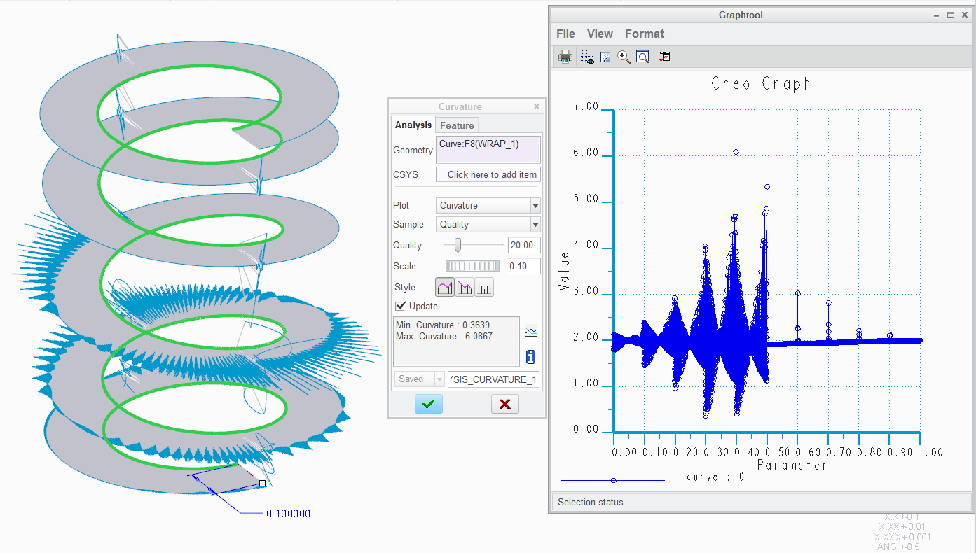
Lesson learned... don't wrap equation curves around cylinders! Hopefully PTC will fix this in Creo 2.0 and 3.0.
This has some pretty serious implications in areas where equations are being used for turbine features wrapped onto cylinders or cones.
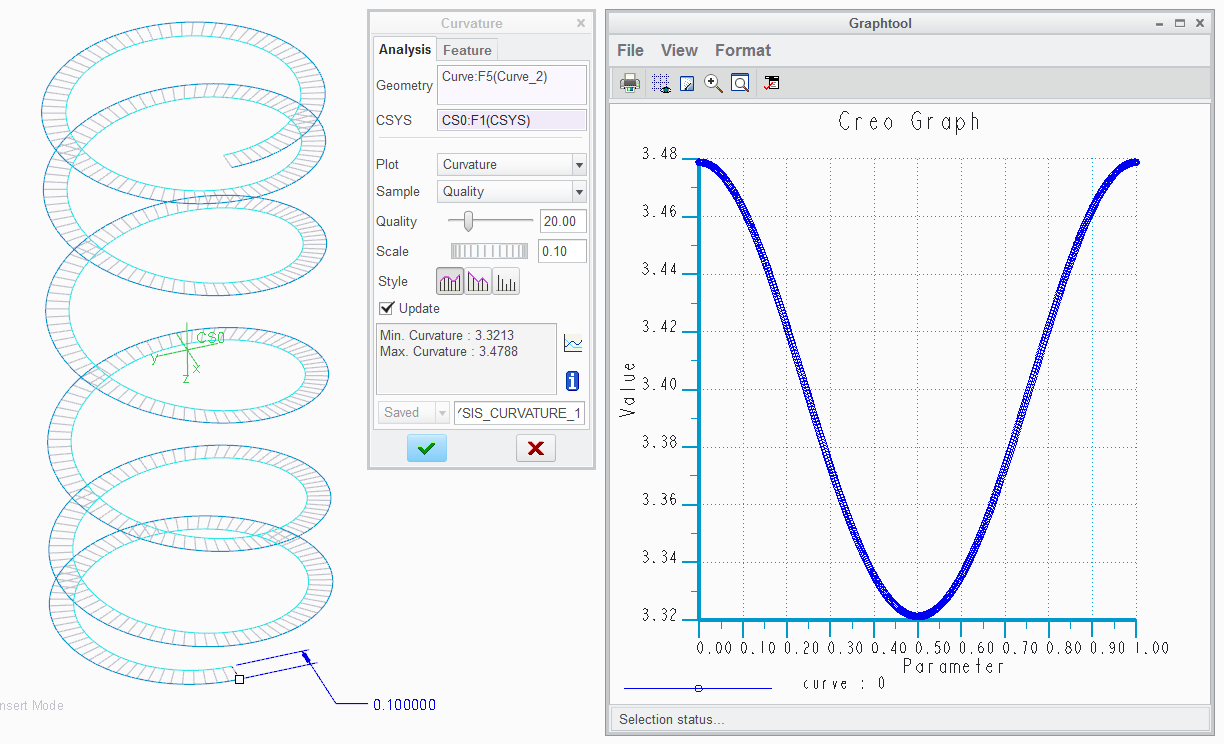
However, even with a single iteration, there are problems that we normally live with. This is back to default accuracy (Relative 0.0012).
This is the curve itself... near perfect:
And then the surface created to create the edge needed for the normal control for the spring below...
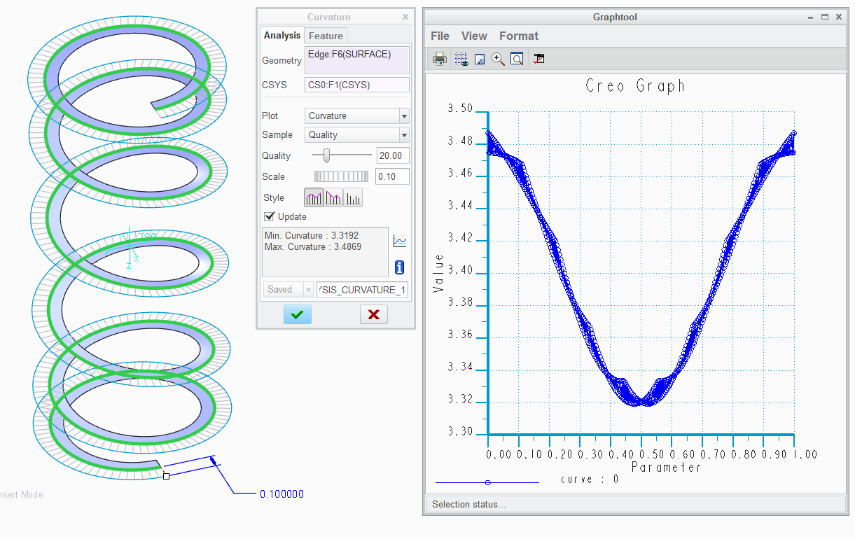
Although for most of us, these small errors are less that catastrophic.
Awareness of the fact that cumulative error will have consequences is something to take note of.
On another note, I would be remiss by not providing a solution.
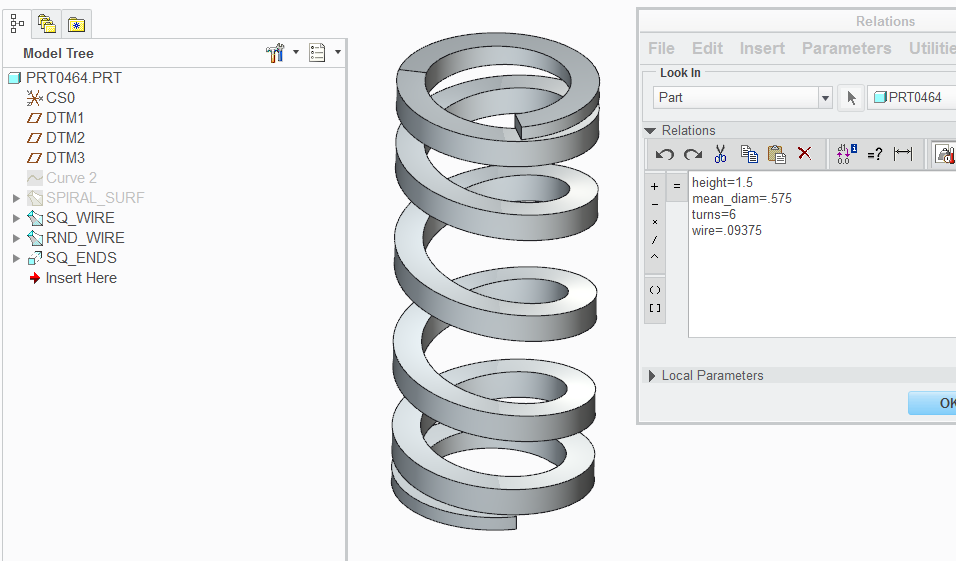
Attached is a Creo 2.0 spring that uses the cylindrical curve from equation. The Pro|WorkAround^TM to the twisting problem is in a surface sweep.
Sweep has a normal to surface option that is not there when the sweep is not generated from a surface... such as the equation curve.
A 4 family table versions of the accurate version is attached...

Driving parameters
Jul 24, 2014
06:55 PM
- Mark as New
- Bookmark
- Subscribe
- Mute
- Subscribe to RSS Feed
- Permalink
- Notify Moderator
Please log in to access translation
Jul 24, 2014
06:55 PM
Never did use Wrap to make springs. It's too difficult to control what you get. Plus it ruins the extents for the part.
http://communities.ptc.com/docs/DOC-3063
To prevent the weird twist seen in Sweep-artifact-g.png, create a second curve with an constant increment added to the radius and it can be used for X-direction control in a variable section sweep.
Jul 24, 2014
07:18 PM
- Mark as New
- Bookmark
- Subscribe
- Mute
- Subscribe to RSS Feed
- Permalink
- Notify Moderator
Please log in to access translation
Jul 24, 2014
07:18 PM
The evalgraph() is definitely a nice way to manage the extent of the part.
But how do you get an equation into the graph feature?
I thought about the second curve to manage the X-direction.
Jul 24, 2014
08:05 PM
- Mark as New
- Bookmark
- Subscribe
- Mute
- Subscribe to RSS Feed
- Permalink
- Notify Moderator
Please log in to access translation

Jul 24, 2014
08:15 PM
- Mark as New
- Bookmark
- Subscribe
- Mute
- Subscribe to RSS Feed
- Permalink
- Notify Moderator
Please log in to access translation
Jul 24, 2014
08:15 PM
It's almost like I've done this before, so I was confident a second equation would help.
If you have an equation I suppose you could use that in place of the evalgraph for that variable in the relation.
Jul 24, 2014
08:18 PM
- Mark as New
- Bookmark
- Subscribe
- Mute
- Subscribe to RSS Feed
- Permalink
- Notify Moderator
Please log in to access translation
Jul 24, 2014
08:18 PM
Not sure if this avoids the problem you already have, but also found this:
Tip: Using the Graph as a Result of the Analysis Feature
When you create an analysis feature using a UDA made on curve or edge, you have the ability to create a datum graph. The x-axis of the graph represents the curve Length parameter that varies from 0 to 1 along the curve or edge. The y-axis represents the computed UDA value as a function of the curve Length parameter.
You can create feature parameters using an analysis feature of relation type to capture the values from this graph.
Suppose the analysis feature creates the graph (containing the UDA) called analysis1. You can create a relation initial_value = evalgraph(analysis1,0) that sets the value of the floating point real parameter initial_value to the y-axis value which corresponds to the x-axis value of 0 in the graph of analysis1. You can now use initial_value parameter just like any analysis feature parameter in a sensitivity, optimization, or feasibility study. For example, you can study the effect of some model dimensions on the initial value of the graph.
Jul 24, 2014
08:22 PM
- Mark as New
- Bookmark
- Subscribe
- Mute
- Subscribe to RSS Feed
- Permalink
- Notify Moderator
Please log in to access translation
Jul 24, 2014
08:22 PM
The fact that this makes sense should scare me! 
Jul 25, 2014
04:00 PM
- Mark as New
- Bookmark
- Subscribe
- Mute
- Subscribe to RSS Feed
- Permalink
- Notify Moderator
Please log in to access translation
Jul 25, 2014
04:00 PM
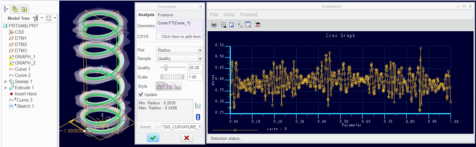
Evalgraph() also causes some very choppy curvatures...
The curve equation is as follows based on a cosine-approximation spline in the graph:
r=ID/2
theta=t*360*TURNS
z=evalgraph("graph_1",t)*LENGTH
The "distortions" improves with higher accuracy settings, but the take-away is still that this is highly inaccurate geometry which make follow on features even more distorted. I am beginning to see why section views tend to fail so often with revolved and swept features.
However, the original observation about the Wrap feature and the subsequent sweep is outstanding in that it is greatly affected at the "invisible" seams of cylinders. At the very least, I hope this can be addressed by PTC engineering.
Still need to figure out how to get a true equation curve into the Graph feature.
Jul 25, 2014
04:30 PM
- Mark as New
- Bookmark
- Subscribe
- Mute
- Subscribe to RSS Feed
- Permalink
- Notify Moderator
Please log in to access translation
Jul 25, 2014
04:30 PM
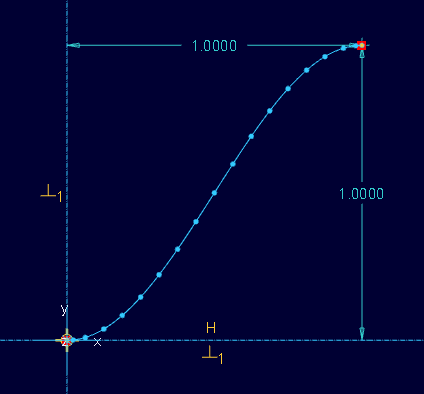
Duh! Create the curve from equation (cartesian): (1x1)
- x=t
- y=.5+cos(t*180)/2*-1
Create a sketch and project the curve into the sketch
Save the sketch into your sketch palette (adding this to the sketch palette is optional but useful for future use)
Create an Graph datum feature and insert the saved sketch (1:1 at 1unit x 1unit recommended for consistency; preserve the original definition since this is a unreferenced projection!).
Add the CSYS in the Graph sketch
...and accept.
 (attached)
Next, use the evalgraph() for the value in the cylindrical curve.
tip: remember to use quote marks around the sketch name! You won't find that in help and gets me every time!
- r=.5 <= radius
- theta=t*360*5 <= number of turns
- z=evalgraph("<graphname>",t)*2 <= actual length of coil
This gets around the seams of the cylinder used before but it still has the coarseness of an interpolated curve (for lack of better term).
This also gets around the bounding box size.
Of course, you can now delete the curve and sketch created to get the graph.
Thanks for your help on this, David!
Jul 25, 2014
05:05 PM
- Mark as New
- Bookmark
- Subscribe
- Mute
- Subscribe to RSS Feed
- Permalink
- Notify Moderator
Please log in to access translation
Jul 25, 2014
05:05 PM
It looks like PTC could do a better job on matching at least the first derivative.
It isn't clear whether follow-on geometry is adversely affected to a noticable extent. It's possible that the curvature analysis sampling is based on the generated mesh / line segment approximation of the curve . A follow-on feature should use the underlying feature definition. I would hope the internal definition would be driven by a piecewise cubic spline or other curve that enforces first and second derivative and passing though the points.
Jul 25, 2014
05:28 PM
- Mark as New
- Bookmark
- Subscribe
- Mute
- Subscribe to RSS Feed
- Permalink
- Notify Moderator
Please log in to access translation
Jul 25, 2014
05:28 PM
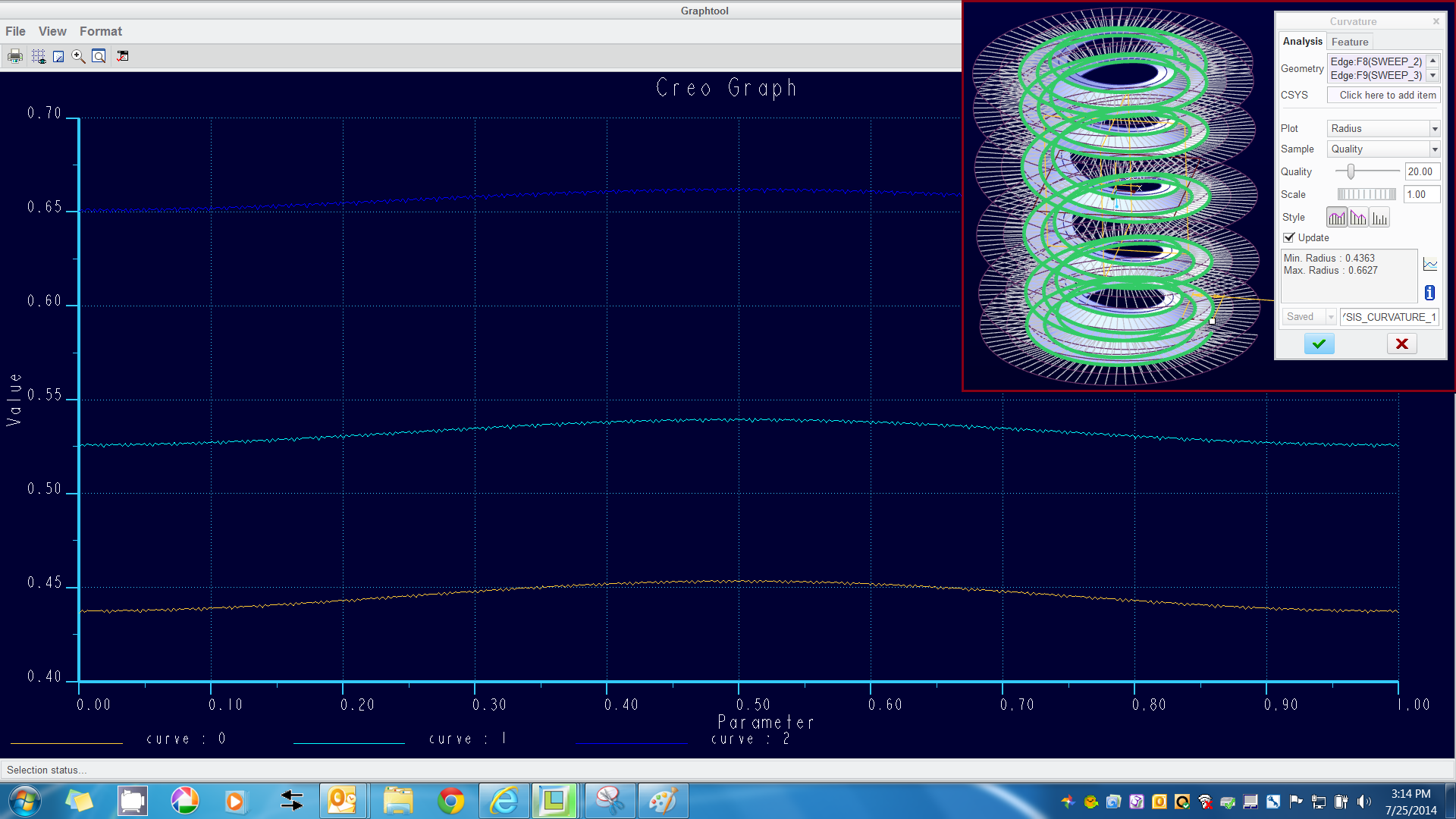
I will let you interpret this result. This is the grapheval() curve with 3 consecutive sweeps:
Jul 25, 2014
05:55 PM
- Mark as New
- Bookmark
- Subscribe
- Mute
- Subscribe to RSS Feed
- Permalink
- Notify Moderator
Please log in to access translation
Jul 25, 2014
05:55 PM
It's consistent. What do you mean consecutive sweeps?
I think an excellent blog for PTC to start is "How this function/feature actually works" to explain the nitty-gritty of this sort of thing.
Jul 25, 2014
06:24 PM
- Mark as New
- Bookmark
- Subscribe
- Mute
- Subscribe to RSS Feed
- Permalink
- Notify Moderator
Please log in to access translation
Jul 25, 2014
06:24 PM
I used the curve to define a swept line (outward) 1/8" long; used that edge to sweep a new line (45 degrees, 1/8" long)... and used that edge for a 3rd sweep. The graph shows all 3 edges.
When I do this with a curve using a pure cosine equation, all 3 are very smooth.
- r=mean_diam/2
- theta=t*360*turns
- z=(height/2)*cos(t*180)
..but the curve from the Wrap feature would not even recognize the edge of a swept edge for analysis because all the semi-arc tangencies were corrupt.
I would love to see PTC engineering weigh in issues like this.
Again, the severity of this issue doesn't show up with arcs or lines wrapped on a cylinder, only an equation curve becomes corrupted to this extent. But an equation curve itself is near perfect!
Jul 25, 2014
06:51 PM
- Mark as New
- Bookmark
- Subscribe
- Mute
- Subscribe to RSS Feed
- Permalink
- Notify Moderator
Please log in to access translation
Jul 25, 2014
06:51 PM
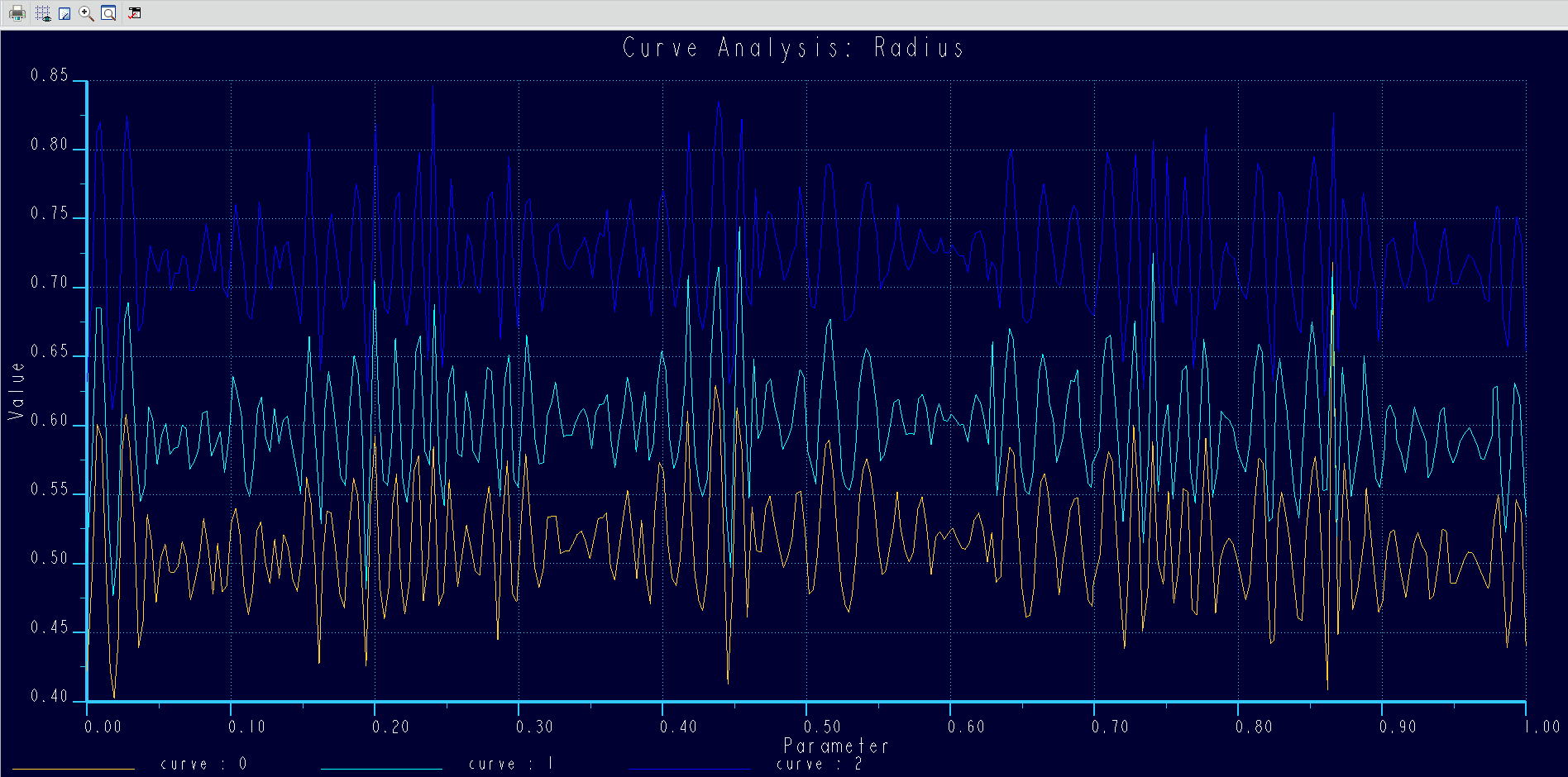
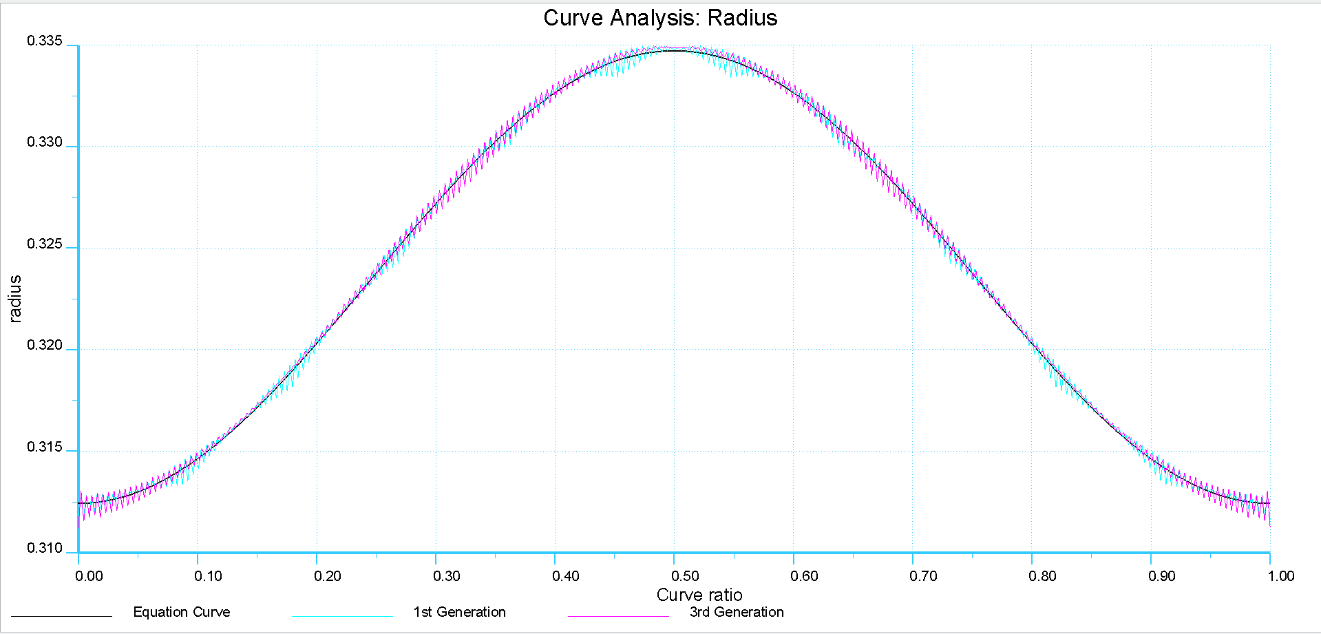
This is a comparison of the initiating curve (cylindrical half wave cosine) and the results from the edge of a swept surface along that curve. Accuracy is default.
This is the analysis of the 3rd generation edge sweep...
And then there is this one... I had the 3rd generation come back to the 1st but not referenced to the 1st.
This overlays all 3 curves.
The excel output is attached.
Jul 25, 2014
07:36 PM
- Mark as New
- Bookmark
- Subscribe
- Mute
- Subscribe to RSS Feed
- Permalink
- Notify Moderator
Please log in to access translation
Jul 25, 2014
07:36 PM
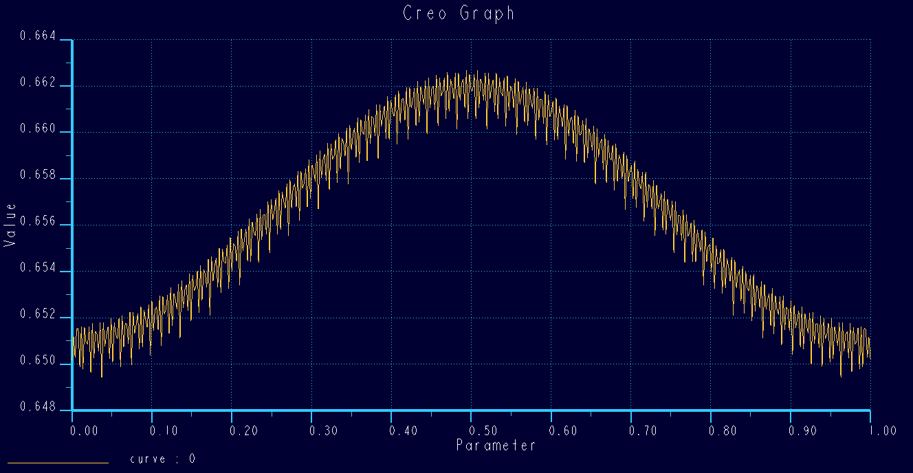
Next was the evaluation of the EvalGraph version. Definitely cumulative!
The black is the curve reference; the second is the edge of the 1st sweep, and the 3rd is the last sweep
I swept a line out, down, back, and return (square box) with a series of 4 sweeps. The 1st iteration was reasonably true to the master, but the 4th generation was seriously flawed.
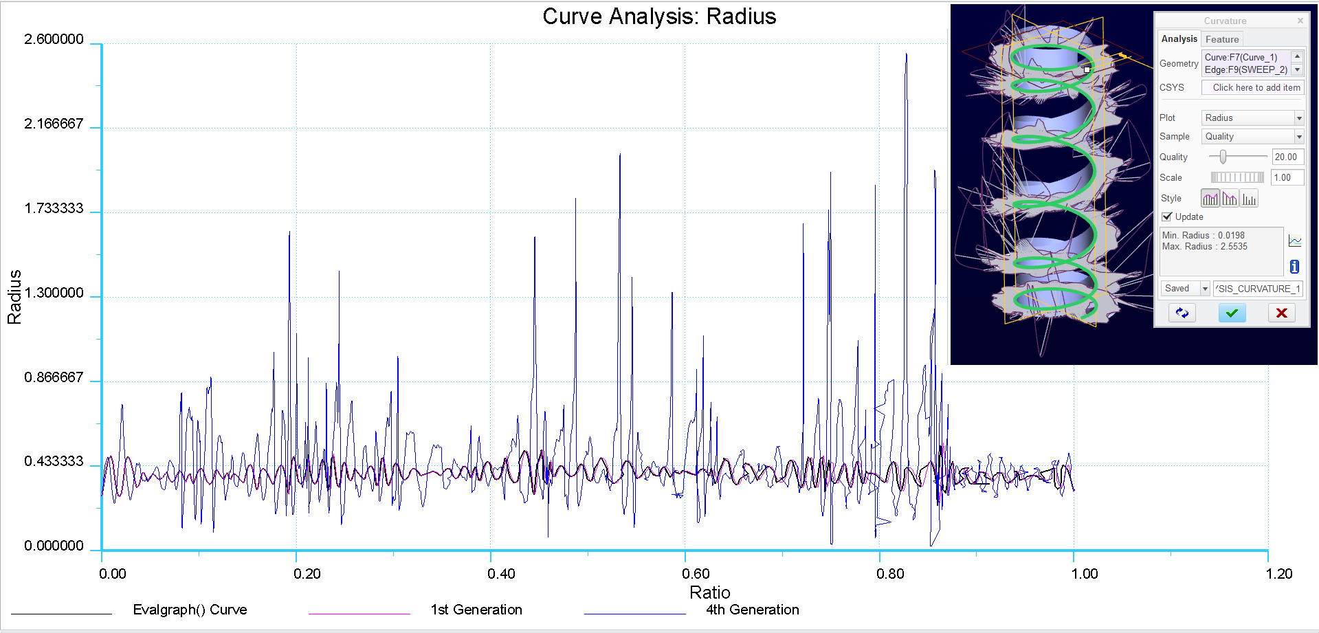
Excel and part file attached. Creo 2.0 full version.
Jul 25, 2014
08:05 PM
- Mark as New
- Bookmark
- Subscribe
- Mute
- Subscribe to RSS Feed
- Permalink
- Notify Moderator
Please log in to access translation
Jul 25, 2014
08:05 PM
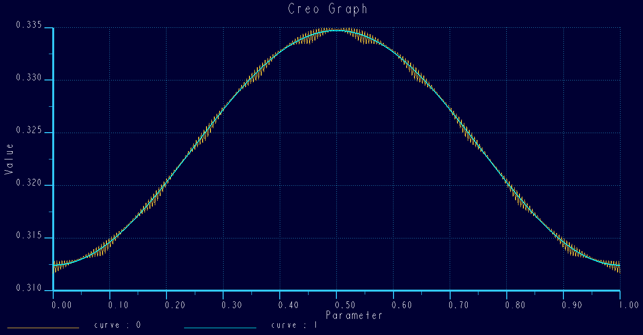
Apples to apples...
This is 4 generations making the same square profile as above. Part file and excel file included.
There is some sign of cumulative error but the error margin remains reasonably well contained.
Refer to the middle of the graph where it deviates from the baseline.
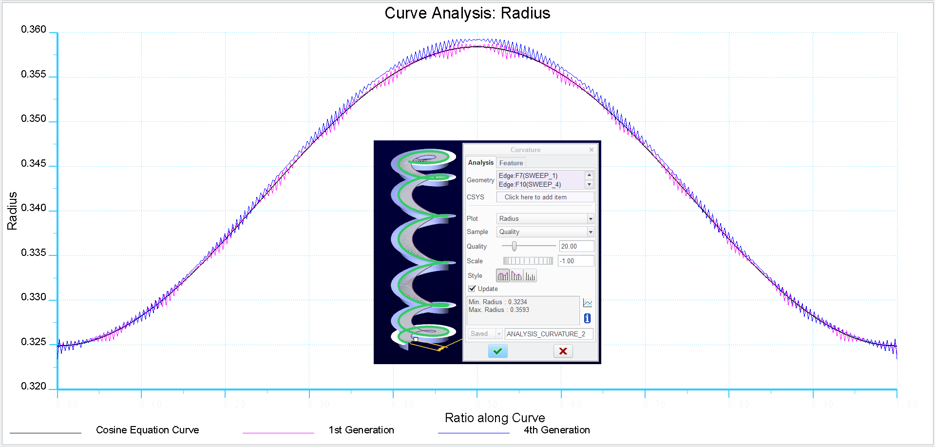
Creo 2.0 full version...
Jul 31, 2014
01:07 PM
- Mark as New
- Bookmark
- Subscribe
- Mute
- Subscribe to RSS Feed
- Permalink
- Notify Moderator
Please log in to access translation
Jul 31, 2014
01:07 PM
Interesting, either I've never had those issues or never noticed them.
I HAVE noticed an issue with features crossing one of the 3 primary datum planes (way back in '96 on v15), and solved it by creating a new set of planes at 45deg around the Y axis. Try creating the cylinder or cylindrical curve by equation so that ALL geometry is in positive X, Y, and Z space. I feel strongly that Pro/E has rounding errors when it approaches "0" in any plane like that, especially where it wants to split the cylindrical surface.
Edit: I just changed the cross section of my wrapped spring from circular to square, and did not see any of the twisting you're seeing Antonious. Weird......
Jul 31, 2014
02:09 PM
- Mark as New
- Bookmark
- Subscribe
- Mute
- Subscribe to RSS Feed
- Permalink
- Notify Moderator
Please log in to access translation
Jul 31, 2014
02:09 PM
Interesting observation.


