Community Tip - Have a PTC product question you need answered fast? Chances are someone has asked it before. Learn about the community search. X
- Community
- Creo+ and Creo Parametric
- 3D Part & Assembly Design
- Anyone using the Analysis measure tools?
- Subscribe to RSS Feed
- Mark Topic as New
- Mark Topic as Read
- Float this Topic for Current User
- Bookmark
- Subscribe
- Mute
- Printer Friendly Page
Anyone using the Analysis measure tools?
- Mark as New
- Bookmark
- Subscribe
- Mute
- Subscribe to RSS Feed
- Permalink
- Notify Moderator
Anyone using the Analysis measure tools?
I’m leading a project to revamp the measure tools (Analysis > Measure). The main goal of the project is to improve the user experience but in order to ensure that our vision for improving the tool is in alignment with the user community, it would be helpful to gather the following information from as many users as we can.
- Do you use the existing measure tool?
- If yes
- What do you like about it?
- What could be improved?
- What types of measurements are you performing? For what purpose?
- How is this information used? Does this information get passed downstream? In what format? (email, parameter in the model, in a table on a drawing, etc)
- Would it be useful to display this information in a persistent note, annotation or other type of feature?
- If no, why not?
- Is it too difficult to use?
- Is it not necessary for your job function?
- If yes
- Any additional comments or information on how the tool is used are welcome. The more details we get the better we can design the new User Interface.
Thanks in advance for your input!
Rosemary Astheimer
PTC Product Manager Data Exchange and Interoperability
This thread is inactive and closed by the PTC Community Management Team. If you would like to provide a reply and re-open this thread, please notify the moderator and reference the thread. You may also use "Start a topic" button to ask a new question. Please be sure to include what version of the PTC product you are using so another community member knowledgeable about your version may be able to assist.
- Labels:
-
Data Exchange
- Mark as New
- Bookmark
- Subscribe
- Mute
- Subscribe to RSS Feed
- Permalink
- Notify Moderator
It would be nice if it were possible to measure something like a theoretical intersection of a point without having to create a sketch ect.
Ex: Analysis > Point to Point. Have a point tied to a plane, then a taper. Then any other point on the other side of the same taper.
Would help when I check the size of a taper without having to open up the drawing or create a sketch. Many other uses I could imagine as well.
Brian Lasker
Design Checker
- Mark as New
- Bookmark
- Subscribe
- Mute
- Subscribe to RSS Feed
- Permalink
- Notify Moderator
I use them to run the Behavior analysis module (actually you have to have them created as features) to be able to create sensitivity, feasibility, or optimization analysis. These behavior analyses need the feature parameters that are created within the analysis features. It would be nice if they could display their references and the actual measurement like an Evaluate feature for trouble shooting purposes.
Mike
- Mark as New
- Bookmark
- Subscribe
- Mute
- Subscribe to RSS Feed
- Permalink
- Notify Moderator
I use the Analysis Measure tools all of the time.
My "wish list" would be that the measure results Distance = X.XXX between two points, edges, etc. also give the X, Y & Z measurements automatically relative to the ASM Datum Planes or PRT Datum Planes. When measureing clearances or distances between features on different parts, it is extremely difficult to get an accurate measurement, other than free space 3D distance measured, which is usually not helpful.
I would also like to see the results in dual units; ie., inches & millimeters, not just the system default units.
It would also be nice to not have the macro box default back to filter "All" when I already have it set to edge or axis in the projection direction. When I have filters already set, it would be nice to keep them that way.
Thanks!
- Mark as New
- Bookmark
- Subscribe
- Mute
- Subscribe to RSS Feed
- Permalink
- Notify Moderator
I use the tool all the time, mostly to measure distances within an assembly. There are several specific geometric measurements that should be added such as Diameter of an edge (only gives Diameter of a cylindrical surface now), but my number one complaint is that it doesn't default to a Surface/Datum Plane selection with Query Select for Edges. This is the way it used to work. It makes more sense and is much faster 90% of the time. It's really mind-blowing to hover over a nice big primary part surface and have the system pick some hidden edge by default. There are other places besides Analysis where this default has been lost, and I still find it very irritating. It seems that changes were made to greater generality rather than keeping a default representing the commonest cases. (Another example is that when you create a Datum Plane thru Axis, then pick another Plane for reference it defaults to Offset when it should default to Parallel which is the MUCH more common case.)
- Mark as New
- Bookmark
- Subscribe
- Mute
- Subscribe to RSS Feed
- Permalink
- Notify Moderator
I'd also like to be able to quickly measure 3 perimeter dimensions in X, Y and Z directions according to objects local coordinate system or global CS of the assembly.
Anyway edge to edge measurement doesn't work on such CAD like Pro/E is? That's shamefull at least.
- Mark as New
- Bookmark
- Subscribe
- Mute
- Subscribe to RSS Feed
- Permalink
- Notify Moderator
I use the Analysis Measure Tools all the time - specifically, part/component interference checks. This feature alone has spared
many-a-tooling change by running this before tooling/product release.
"What do I like about it?"
It checks for interferences between parts, surfaces...
"What could be improved?"
Probably better definition of the interference...
I also use draft check quite often.
"What could be improved?"
Much earlier versions of Pro-E had a greater gradient output when running the draft check as compared
to WF5.0 - I liked the greater gradient...
Thanks for asking for input Rosemary - Good Luck!
Regards,
Bob Barker
- Mark as New
- Bookmark
- Subscribe
- Mute
- Subscribe to RSS Feed
- Permalink
- Notify Moderator
Thank you to everyone who has replied. I've been pleasantly surprised at the consistency of everyone's feedback, which makes it easier to prioritize what needs to be done. Here are the underlying themese that I've observed:
- The UI needs improvement
- Combine the existing 9 measure tools into one ribbon.
- If you change the type of measurement that you want to make or if you want to make several measurements you should not have to "Cancel" out of the dialog.
- Make the measurements intelligent (i.e. If you select a surface you probably want the surface area and perimeter, if you select a curve you probably want the curve length, if you select two edges you might want the minimum and maximum distance, etc.)
- the current tool returns a single value which may not be what you were looking for
- Today when measurements are saved, they are "hidden" and not easy to access (compared to annotations which show int he model tree).
- I envision a history of measurements that have been taken in session that are easily copied, transferred to a parameter or perhaps even stored in an annotation feature. Of course we will have to see if any of these options are possible.
- If measurements are saved, they cannot be moved and their appearance cannot be modified.
- Again, I would like to see some of the same capabilites tha are available for annotations applied to the measure tools.
- Combine the existing 9 measure tools into one ribbon.
- Selection of the geometry is painful. Often underlying geometry is selected rather than the geometry closest to the screen and having to change the selection filter from the default setting of "All" adds one more step to the process.
- There are a few new measurement options (such as measure from a theoretical intersection) that should be considered.
Of course there several other items that will be improved over time, but I see the above points as the major ones to address first.
Thank you again for taking the time to give your feedback. Look for me at PlanetPTC to get an update on our progress.
Rosemary
- Mark as New
- Bookmark
- Subscribe
- Mute
- Subscribe to RSS Feed
- Permalink
- Notify Moderator
A couple more little things:
1.If I want to measure the length of an edge which returns on itself (like the end of a cylinder) I get only half the edge.
2.The Angle measurement can be confusing; there is a thread somewhere in this forum based on one user's frustration with finding the most obvious included angle between two surfaces.
- Mark as New
- Bookmark
- Subscribe
- Mute
- Subscribe to RSS Feed
- Permalink
- Notify Moderator
There's some relevant discussion in this thread:
- Mark as New
- Bookmark
- Subscribe
- Mute
- Subscribe to RSS Feed
- Permalink
- Notify Moderator
Most of the informationis for the original poster but I wanted to expand on your points.
1) For this one it may be making it more consistent with other selections which has been mentioned in the past. By this I mean sometimes you use CTRL + your edge selections if you are selecting in the graphics window. Two ways to make the measurement for the circular edge are: 1) select the details button under the Curve box entry and you can add the other half. 2) select on the circle and half of it is selected, hold the SHIFT key and it will allow you to select the whole circle edge as a tangent chain which is also a selection method in the graphics window. From the help document it isn't clear that this is something that needs to be done.
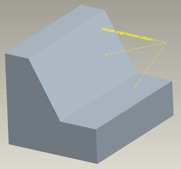
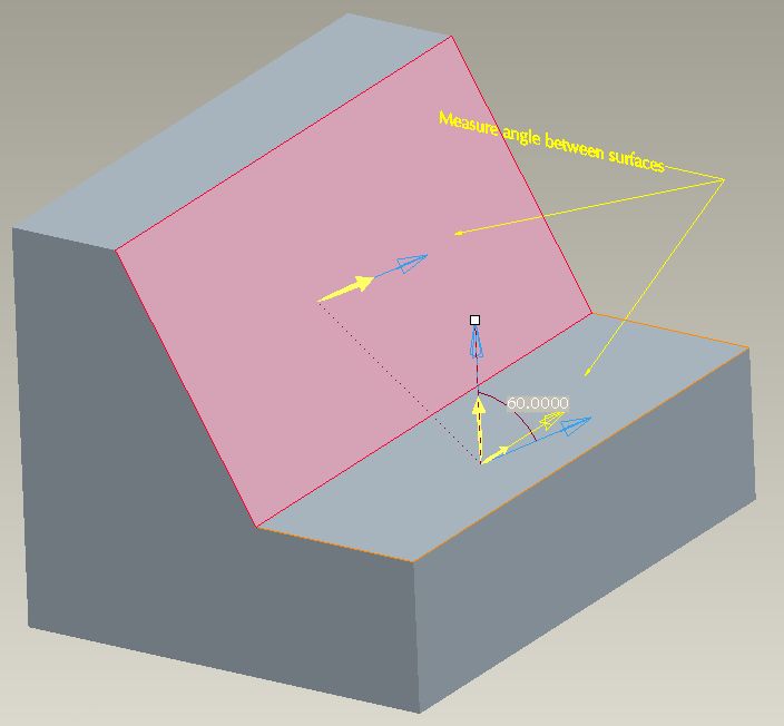
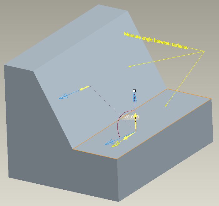
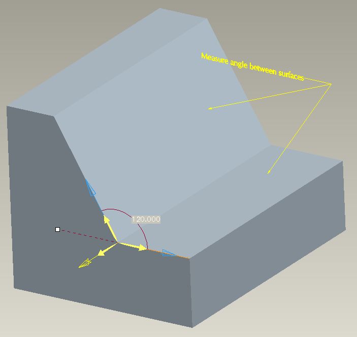
2) I remember this one as I was involved. People get confused with the measurement results because when you select the surfaces it uses the surface normals to measure the angle. This causes people frustration because: 1) the angle they are expecting isn't returned. 2) they manipulate the arrows to get the correct angle but don't understand why it gives them the value they want because the results are displayed rotated 90 degrees to they expect. Here are some images to explain:
You want the angle measurement between the surfaces in the following which is 120:

This is what you get as a measurement:

Flipping the arrows correctly you get the correct measurement but it's rotated 90 from how you expect it to appear:

This is what users are expecting to see which is what you get from selecting the edges:

The question that gets asked is why can't you have the angle measurement appear as expected.


