Community Tip - When posting, your subject should be specific and summarize your question. Here are some additional tips on asking a great question. X
- Community
- Creo+ and Creo Parametric
- 3D Part & Assembly Design
- Re: Are there lybraries containing the blocks, the...
- Subscribe to RSS Feed
- Mark Topic as New
- Mark Topic as Read
- Float this Topic for Current User
- Bookmark
- Subscribe
- Mute
- Printer Friendly Page
Are there lybraries containing the blocks, the wires made?
- Mark as New
- Bookmark
- Subscribe
- Mute
- Subscribe to RSS Feed
- Permalink
- Notify Moderator
Are there lybraries containing the blocks, the wires made?
Hello guys,
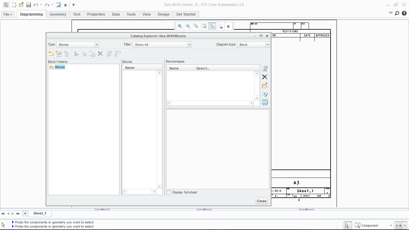
I have one question about the lybraries of the Creo Schematic 3.0, Is there a link where I can download
the lybraries with some symbols to make a circuit diagrams because when I create a new design there
are not the symbols As shown in this picture...

- Labels:
-
Routed Syst. Design
- Mark as New
- Bookmark
- Subscribe
- Mute
- Subscribe to RSS Feed
- Permalink
- Notify Moderator
I don't know of any pre-made libraries (Virtual Interconnect sells libraries of parts to use to make your own blocks and groups).
Suspect that it is because everyone's style is different. Every so often someone at work asks if we are following a standard and I have to explain that none of the standards are actually useable. We decided to create our library to look very similar to our previous schematics.
The symbol drawing tools (the Geometry tab) are reasonably easy and quick if you ignore 95% of it that was written for a 2D mechanical cad system.
The key things I use are line (thin solid, medium solid, thin dotted), rectangle and the edit line features of Arc and Segment Visibility. I use Arc to create circles since it allows me to make them as part of a line with multiple segments that can be moved or copied as a whole.
There is no fill for solid colored shapes. The best you can do is use a cross hatch pattern with the lines spaced close together. The cross hatch tool has some significant issues due to its former life in mechanical cad and could take a lot of explaining to work well. The big hint is to set the line spacing as you are creating the initial hatch. The default spacing is 5mm which will not show up in most schematics uses like diode symbols.
There is a lot to learn. We are big enough that we hired a consultant to help us get started, including a lot of details of how we would work with schematics and training in how to use it. It was a lot cheaper than learning it all by experiment.
- Mark as New
- Bookmark
- Subscribe
- Mute
- Subscribe to RSS Feed
- Permalink
- Notify Moderator
Hi,
You can do one of the following :
- You can check Virtual interconnect (in Get Started tab-> Online library will get you to their site);
- You can use Sample Catalog provided with Creo Schematics (in Get Started tab->Sample Catalog)
- Create your own catalog (it can be based on the sample catalog...)
Best Regards,
Gaby


