
Turn on suggestions
Auto-suggest helps you quickly narrow down your search results by suggesting possible matches as you type.
Showing results for
Please log in to access translation
Turn on suggestions
Auto-suggest helps you quickly narrow down your search results by suggesting possible matches as you type.
Showing results for
- Community
- Creo+ and Creo Parametric
- 3D Part & Assembly Design
- AutoGEM Settings
Translate the entire conversation x
Please log in to access translation
Options
- Subscribe to RSS Feed
- Mark Topic as New
- Mark Topic as Read
- Float this Topic for Current User
- Bookmark
- Subscribe
- Mute
- Printer Friendly Page
AutoGEM Settings
Oct 01, 2012
09:21 AM
- Mark as New
- Bookmark
- Subscribe
- Mute
- Subscribe to RSS Feed
- Permalink
- Notify Moderator
Please log in to access translation
Oct 01, 2012
09:21 AM
AutoGEM Settings
I've just noticed that there are some options in AutoGEM Settings that I haven't used before.
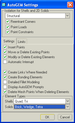
In particular:
- What does Detailed Fillet Modeling do? At present I apply an Edge Length by Curvature control on any critical fillet surfaces; would this option be better?
- I've only just noticed that you can change the solid element type from just Tetra to include Wedge and Brick. Are there any reasons not to do this, when working with solid geometry?
This thread is inactive and closed by the PTC Community Management Team. If you would like to provide a reply and re-open this thread, please notify the moderator and reference the thread. You may also use "Start a topic" button to ask a new question. Please be sure to include what version of the PTC product you are using so another community member knowledgeable about your version may be able to assist.
Labels:
- Labels:
-
General
1 REPLY 1
Oct 11, 2012
01:26 PM
- Mark as New
- Bookmark
- Subscribe
- Mute
- Subscribe to RSS Feed
- Permalink
- Notify Moderator
Please log in to access translation
Oct 11, 2012
01:26 PM
Detailed fillet modelling globally introduces more elements in, and as a consequence, near fillets. This seems to happen when the the fillet arc length is about 10% the size of a neighbouring element. Not sure what the rule applied is, if it were length by curvature then the mesh would be different to that I observed.
I use ELC at specific, required locations only. Although I have to admit the (edge length/rad) ratio seems to me to be the wrong way up.
Brick,wedge meshing becomes useful for thin structures. Thin things are inefficiently filled by tets. Create a plate and remesh with Brick, wedge, tetra on. For thick plates - only tets, as you reduce the thickness of the plate there is a critical aspect ratio where the mesher goes for bricks and wedges over tets.
If you have geometry that has thin areas (bricks and wedges) and thick bits (will get tets) then you could use Brick wedge and tetra. Just thin - brick wedge.
With thick bits poking out from a thin surface you are likely to get some face to face links where it needs to 'join' the triangular tets to the square faces of the wedge and bricks. Having said that, as I remember, it created links if it was just wedge and tet, depsite the wedges presenting a triangular surface.
In the past, I've 'volume regioned' off the thick bits and separately meshed these volumes as tets only, (you may have to limit the size with an autogem control so that it marries well with the neighbouring thin bit when you come to mesh this). saving the mesh, switching the settings to wedge and tet (not brick), retrieving the mesh and then finishing by meshing the thin volumes as a second operation. This looses the bricks and the links. If you leave the bricks in you get the links back.
You can't switch the settings in the middle of meshing without losing the mesh. The switching prevents Autogem attempting to mesh with inappropriate elements, complaining and then settling for tets.
It's a bit of a faff but has saved a large number of elements in some models, particularly good for those repeated runs (time)
NB. if the part has a material propery assigned then everything gets meshed regardless of volume selected.


