
Turn on suggestions
Auto-suggest helps you quickly narrow down your search results by suggesting possible matches as you type.
Showing results for
Please log in to access translation
Turn on suggestions
Auto-suggest helps you quickly narrow down your search results by suggesting possible matches as you type.
Showing results for
Community Tip - Did you get called away in the middle of writing a post? Don't worry you can find your unfinished post later in the Drafts section of your profile page. X
- Community
- Creo+ and Creo Parametric
- 3D Part & Assembly Design
- Beam element not behaving as expected.
Translate the entire conversation x
Please log in to access translation
Options
- Subscribe to RSS Feed
- Mark Topic as New
- Mark Topic as Read
- Float this Topic for Current User
- Bookmark
- Subscribe
- Mute
- Printer Friendly Page
Beam element not behaving as expected.
Apr 11, 2013
02:17 PM
- Mark as New
- Bookmark
- Subscribe
- Mute
- Subscribe to RSS Feed
- Permalink
- Notify Moderator
Please log in to access translation
Apr 11, 2013
02:17 PM
Beam element not behaving as expected.
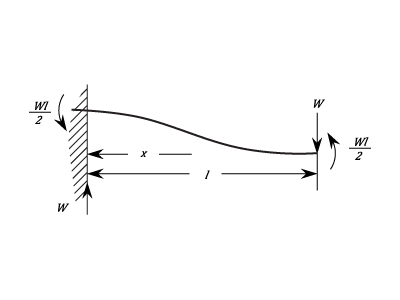
I have an assembly where I am modeling an anchor from a structure into concrete with a beam element and conducting a modal analysis. The end of the beam in the concrete is constraint in all 6 DOF and the other end is connected to the structure via a weighted link. The base of the structure is contratined to prevent vertical translation (y). The net result of all of this should be a fixed end-guided end beam condition (shown below).
However, when I look at a deformed plot of my model, it looks like the "fixed end" is allowing rotation. The beam is not going through a "S" shape deformation and it looks as if there is rotation on the fixed end. The constrains on the top is defined on the surface of shell elements.
I have comfirmed that there are not any beam releases defined.
Any thoughts?
This thread is inactive and closed by the PTC Community Management Team. If you would like to provide a reply and re-open this thread, please notify the moderator and reference the thread. You may also use "Start a topic" button to ask a new question. Please be sure to include what version of the PTC product you are using so another community member knowledgeable about your version may be able to assist.
Labels:
- Labels:
-
Assembly Design
4 REPLIES 4
Jul 24, 2013
05:49 AM
- Mark as New
- Bookmark
- Subscribe
- Mute
- Subscribe to RSS Feed
- Permalink
- Notify Moderator
Please log in to access translation
Jul 24, 2013
05:49 AM
It's better to use a rigid link in this case. The weigted link allows rotation.
Jul 24, 2013
01:44 PM
- Mark as New
- Bookmark
- Subscribe
- Mute
- Subscribe to RSS Feed
- Permalink
- Notify Moderator
Please log in to access translation
Jul 24, 2013
01:44 PM
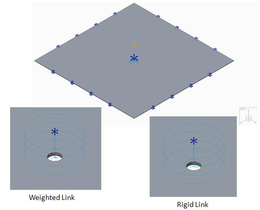
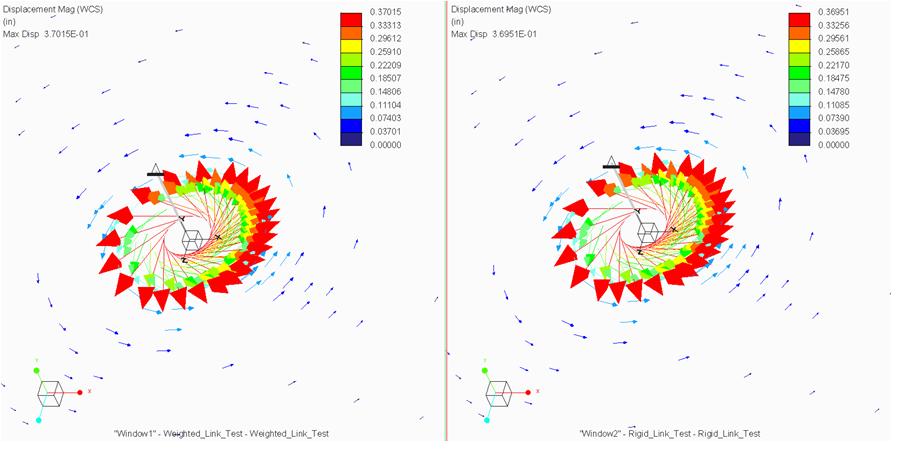
I know that the weighted link only gives TX, TY, and TZ control, but are you sure that it allows rotation? I only ask because I made a very basic model of a plate with a hole in the center and a beam element with one end co-planner with the top surface of the plate and the other end 1/2" above the plate. The beam end above the plate had 5 DOF locked and the 6th DOF set to a 3.14 rad perscribed rotation (about the beam's own axis). The outer edges of the plate were constrained as well (plate was modeled with shell elements). The co-planner end of the beam element was attached to the edge of the hole with a weighted link (in one analysis) and a rigid link in another analysis. Below is an image of the model setup.
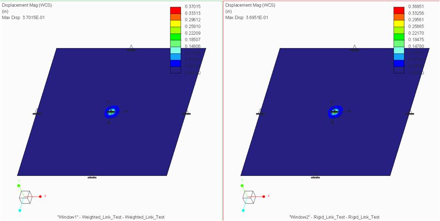
A contour plot of the displacement (magnitude) shows essentially the same values and contour.
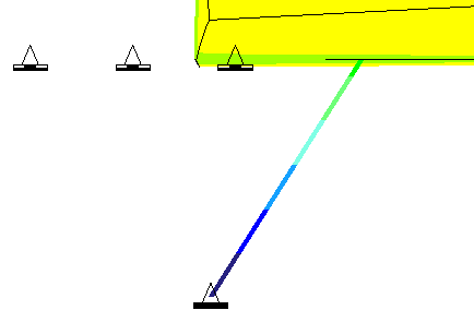
Looking at a vector plot of the results shows the rotation within the shell elements.
Getting back to the original problem I posted, if you look at the end of the beam with the 6 DOF constraint, it looks like the end of the beam is rotating. If it is true that a weighted link will allow rotations, then I'd of a fixed-end, guided-end beam setup, I would expect a fixed-end, guided-pinned.
Jul 25, 2013
04:04 AM
- Mark as New
- Bookmark
- Subscribe
- Mute
- Subscribe to RSS Feed
- Permalink
- Notify Moderator
Please log in to access translation
Jul 25, 2013
04:04 AM
Weighted links are badly described in the documentation.
What it says in the Simulation training tutorial is; 'they do not add stiffness to your model' and, you use them to 'create moment free enforced displacements'
However when you test them, you see that rotations are indeed fixed.
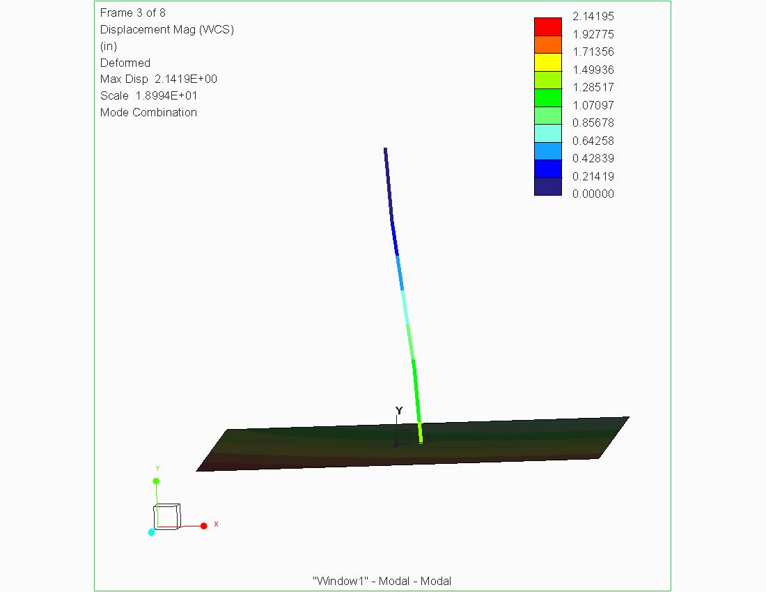
So, I performed you're first Modal simulation. I do get the S shape you were looking for...
So I'm not sure what the difference between our studies is...
Jul 25, 2013
01:11 PM
- Mark as New
- Bookmark
- Subscribe
- Mute
- Subscribe to RSS Feed
- Permalink
- Notify Moderator
Please log in to access translation
Jul 25, 2013
01:11 PM
Hi Shaun,
I'm wondering what output plotting grid number you are using (on the Output tab of the analysis definition dialog). If the number is too low, then it's difficult to see the true deformed shape of the beam. Increasing the output plotting grid number or the number of beam elements might make the curved shape of the beam more obvious.
Tad Doxsee
PTC


