Community Tip - When posting, your subject should be specific and summarize your question. Here are some additional tips on asking a great question. X
- Community
- Creo+ and Creo Parametric
- 3D Part & Assembly Design
- Re: Best Drawing Formats
- Subscribe to RSS Feed
- Mark Topic as New
- Mark Topic as Read
- Float this Topic for Current User
- Bookmark
- Subscribe
- Mute
- Printer Friendly Page
Best Drawing Formats
- Mark as New
- Bookmark
- Subscribe
- Mute
- Subscribe to RSS Feed
- Permalink
- Notify Moderator
Best Drawing Formats
We're refining / updating / improving drawing formats and templates (Creo Parametric 3 with Windchill 10.2).
Looking for "lessons learned" and tips & tricks, etc. on this from all. We have B, C and D - inch / mm.
Would appreciate any example files - especially how you populate various cells parametrically from models.
thanks
This thread is inactive and closed by the PTC Community Management Team. If you would like to provide a reply and re-open this thread, please notify the moderator and reference the thread. You may also use "Start a topic" button to ask a new question. Please be sure to include what version of the PTC product you are using so another community member knowledgeable about your version may be able to assist.
- Labels:
-
2D Drawing
- Tags:
- drawing template
- Mark as New
- Bookmark
- Subscribe
- Mute
- Subscribe to RSS Feed
- Permalink
- Notify Moderator
There are probably a million opinions, but I'll throw out a few of mine.
- I use the drawing grid extensively when building formats. Enable snap to grid and then change the grid spacing while constructing different elements. Very handy.
- I build the different elements separately and then bring them all together on the finished formats. Both the drawing border and the non-changing table text are turned into symbols. This makes it easy to position them and keeps the users from inadvertently changing some aspect of them.
- Be very mindful of the drawing's (or format's) default text height when creating tables. This value get's embedded into the table and is nearly impossible to change. It directly determines the row height, row width, and "buffer" area inside each cell. I find it beneficial to use a smaller default text size while creating the table than what the table text will ultimately be set to.
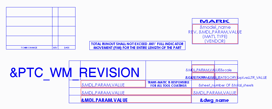
- For dynamic table information, I'm a huge fan of single cell repeat regions. These force the parameter values to be read from the model (and never the drawing), and they don't break (or display anything) if the parameter doesn't exist in the model.
- There is a technique that can be used to create larger, scaled up versions of the drawing tables for larger formats without having to recreate them. It's a two step process using the config option "variant_drawing_item_sizes" and the scale command. Let me know if you need help with this....
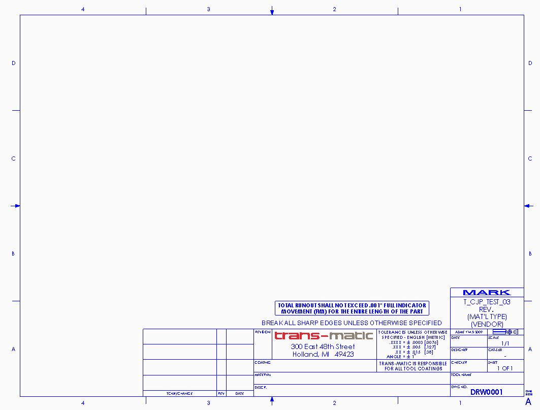
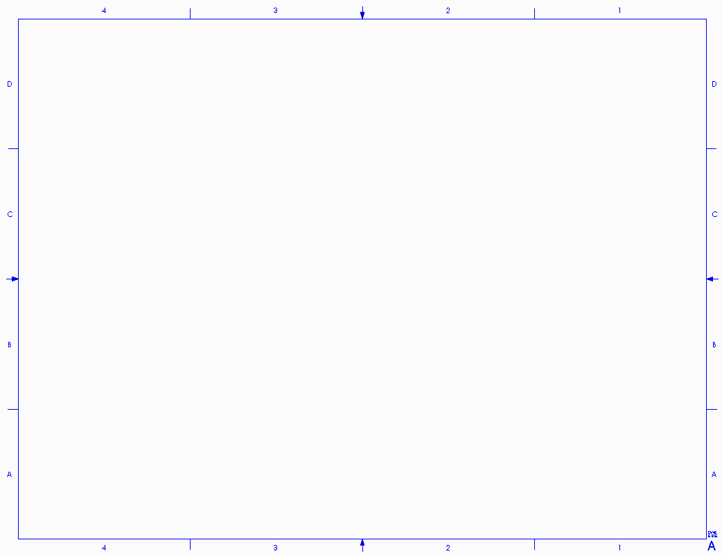
Pictures:
Empty drawing:

Border Symbol (one symbol for each sheet size & orientation):

Title Block Tables (the red boxes are single cell repeat regions):

Title Block Symbol:

- Mark as New
- Bookmark
- Subscribe
- Mute
- Subscribe to RSS Feed
- Permalink
- Notify Moderator
Oh, one more thing. If you don't want to use repeat regions, but you want to make sure to get the model's parameter value instead of the drawing's, you can use the syntax <parameter_name>:mdl . Adding the :mdl at the end will keep the table from evaluating the drawing's parameter value if the parameter doesn't exist in the model. This functionality was added at Creo 2.0 M150 and Creo 3.0 M040. Keep in mind that is can be a little flakey. Sometimes I have to reapply formats that use this syntax after the missing parameter has been created in the model. FWIW.
- Mark as New
- Bookmark
- Subscribe
- Mute
- Subscribe to RSS Feed
- Permalink
- Notify Moderator
All fine tips, however we often create drawings without a model, but out revision/version pulled from PDMlink must come from the drawing file.
Its just something to keep in mind.
The only thing I've done different than most companies is eliminate B and D sizes. Here's why;
First, seldom is anyone printing on B...and D is the same aspect ratio as B. And A,C and E are all the same aspect, which makes allows printing on A-size paper (used 99%) for all 3 sizes. Some people complained at firt because they thought the sheet size determined what size they print. Of course it does not. We can print ANY format size to ANY paper size. Thus, offering 3 drawing sheet/format sizes vs 5 has not posed a single problem.
Second, this significantly reduces the number of formats to maintain and update. We have 6 3D CAD systems throughout our engineering facilities. And I am not counting our ECAD, CAM, or mold or tool drawings using either their own software and/or their own formats.
- Mark as New
- Bookmark
- Subscribe
- Mute
- Subscribe to RSS Feed
- Permalink
- Notify Moderator
We print almost everything on B sized paper, so I wouldn't say that it is seldom used.
That being said, I usually use D formats and print them on B paper in order to get more usable drawing area due to the smaller text size.
It does not meet ANSI specifications this way, but it works for us.
- Mark as New
- Bookmark
- Subscribe
- Mute
- Subscribe to RSS Feed
- Permalink
- Notify Moderator
Dan,
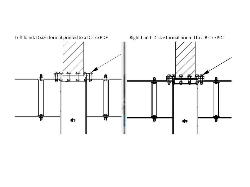
Do you find a loss of quality to the pdf, and too thick of line weights, caused printing a D size format onto a B size pdf sheet?
This is what my company does as well, and I see quite the loss of quality.
Have you found a way to fix this?

- Mark as New
- Bookmark
- Subscribe
- Mute
- Subscribe to RSS Feed
- Permalink
- Notify Moderator
I cannot repeat that, nor have I seen that before.
Seems to be more of an image compression issue than a PDF file issue (not a Creo issue at all). May be try different Adobe reader settings?
- Mark as New
- Bookmark
- Subscribe
- Mute
- Subscribe to RSS Feed
- Permalink
- Notify Moderator
What size of PDF do you select? 11x17 or ANSI D
- Mark as New
- Bookmark
- Subscribe
- Mute
- Subscribe to RSS Feed
- Permalink
- Notify Moderator
Back when we set up our printing, we we made different pen table files for "laser prints" vs "plots". The plots had heavier line weights than the laser prints. If you are creating a B size PDF from a D size drawing, you'll want a pen table file with lighter line weights to avoid what you are seeing.
Alternately, create your PDF full scale and do the scaling when (and if) you print it. In other words, turn your D size drawing into a D size PDF and then print that on your B size laser printer. That's what we do.
- Mark as New
- Bookmark
- Subscribe
- Mute
- Subscribe to RSS Feed
- Permalink
- Notify Moderator
Mike,
You may want to consider using a 2D drawing software (Adobe Illustrator, Autocad, Draftsight, Corel Draw, etc) to create your format borders, save as a DXF (or DRW, I forget which the drawing program can import in template mode), then import it into Creo. Creo's drawing and sketching tools leave much to be desired.
Be careful about how you place your zone letters and numbers. Do not make the same mistake I did and place them in a group; do each one as an individual placement. When Creo converts the font in PDF generation, it can play havoc with the character spacing, especially the space character.


