Community Tip - New to the community? Learn how to post a question and get help from PTC and industry experts! X
- Community
- Creo+ and Creo Parametric
- 3D Part & Assembly Design
- Re: Cam-follower mechanism question
- Subscribe to RSS Feed
- Mark Topic as New
- Mark Topic as Read
- Float this Topic for Current User
- Bookmark
- Subscribe
- Mute
- Printer Friendly Page
Cam-follower mechanism question
- Mark as New
- Bookmark
- Subscribe
- Mute
- Subscribe to RSS Feed
- Permalink
- Notify Moderator
Cam-follower mechanism question
I am working in WF3.
I am modelling a Swedish Navy Sailship from about 1650 and have now come to the guns of the lower decks – the ports should open and the barrells poke out through the openings.
I have modelled a gun-unit which works fine and I am now trying to make a drive-rail running along the line of guns to do the required movement of all ports simultaneously.
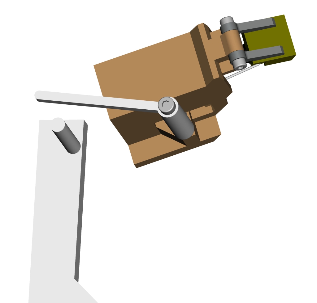
The drive rail moves in a straight line (up and down in the picture below) and should push the lever on the gun-unit to its open position. The return movement of the gun-unit lever will be by means of a spring as the drive rail moves downwards again.
The gun-unit lever move approximately 90°.
I have connected the drive-rail with a gun-unit lever using a slot connection and it works fine.
My problem is that the drive rail has to move a certain distance to move the gun-unit with the largest turning angle and therefore a slot connection is not good enough.
I have tried to use a cam-follower connection using the surface of the little pin on the drive-rail as one part and the surface of side of the gun-unit lever as the other, hoping that a cam-connection with a lift-off property would do the job but Proe will not accept this.
Am I trying to do the impossible? Is such a cam-follower connection not possible?
If somebody wants to have a go at it I would be happy to upload a zip file (16 Mb)
Grateful for any help
Bertil Rogmark

- Labels:
-
Surfacing
- Mark as New
- Bookmark
- Subscribe
- Mute
- Subscribe to RSS Feed
- Permalink
- Notify Moderator
Silly mistake!
Defined the flat cam-surface front and back points incorrectly.
Redefined them and the thing works!
- Mark as New
- Bookmark
- Subscribe
- Mute
- Subscribe to RSS Feed
- Permalink
- Notify Moderator
Don't forget to mark your answer as correct in case someone has the same silly mistake and searches on your post.
Thanks, Dale
- Mark as New
- Bookmark
- Subscribe
- Mute
- Subscribe to RSS Feed
- Permalink
- Notify Moderator
I hope we get to see a video of this is action. ![]()
- Mark as New
- Bookmark
- Subscribe
- Mute
- Subscribe to RSS Feed
- Permalink
- Notify Moderator
Hello Tom,
attached are 2 videos, one showing a single gun_unit and one showing the whole broadside.
My current problem id that while all gun ports open to the same angle, their respective closed position vary as much as 20°.
The current model has cam-follower without the lift-off feature which means that the gun port that has the largest "close" angle prohibits the drive rail to conrinue and close all ports properly.
I do not have the Proe-feature of simulating a rubber-band connection so I cannot simulate the closing movement as desired.
In real life the cam follower would be with lift-off feature and there will be a spring or rubber band pulling the individual gun ports to their correct closed position. Video Link : 7139 Video Link : 7140
- Mark as New
- Bookmark
- Subscribe
- Mute
- Subscribe to RSS Feed
- Permalink
- Notify Moderator
That is really cool! Could you change the point of contact on the levers so each one travels a different distance (to match the angle variation)?
- Mark as New
- Bookmark
- Subscribe
- Mute
- Subscribe to RSS Feed
- Permalink
- Notify Moderator
Yes, you are correct in that the longer the lever contact point moves away from the lever centre, the lever revolving angle for a given drive rail movement is reduced.
It must therefore be possible to find a lever contact point for every gun-unit that, for a certain stroke of the drive-rail, makes the lever turn exactly the desired amount. It would then be possible to use either a slot connection or a cam-follower without lift-off.
Have in mind that the port closed position is absolute. Once the port-lid is flush with the hull it cannot move any further. On the other hand, the port open position is not critical – I am aiming for about 135° from the gun-units’ vertical.
Harsh reality – tolerances when fitting 14 gun-units to a hand built hull and of course the hull itself – makes me scared to have a powered drive rail that may try to force its movement past the closed position of one or several ports.
This is why I am planning to having an excessive stroke on the drive rail and a lift-off cam-follower connection, to make sure that any individual port, powered by a spring, can reach its specific closed position. In the opening direction the cam connection would push all ports to approximately the same position (the 135° mentioned above). It is acceptable that the common open position varies as a result of the building tolerances expected. The gun-units are pretty exact – I am 3d-printing all components of those.
Having said all this – I cannot include my “practical” solution in Proe so I either leave my model as the video show with ports not reaching their proper closed position or model a drive rail with lever contact-points as you suggested and no lift-off function (or a slot connection) in order to have the Proe-model behaving properly. The actual model to be built would have to have returning springs and lift-off function
- Mark as New
- Bookmark
- Subscribe
- Mute
- Subscribe to RSS Feed
- Permalink
- Notify Moderator
Since the closed position is absolute, I would work backwards from there. Set up you drive pins so as you adjust them left and right (for more or less travel) they automatically remain tangent to the lever. Then you just adjust each one left or right however much you need to provide the open position you're looking for. (Of course each time you regenerate you would want to make sure everything was in the closed position but this is easy to do with the connection settings.)
- Mark as New
- Bookmark
- Subscribe
- Mute
- Subscribe to RSS Feed
- Permalink
- Notify Moderator
Hello again Tom,
I have modelled the gun-port movement with cam-followers, no lift-off, and set the pins to achieve exact closed positions and an opening angle equal for all ports.
See video for effect on the (almost) complete ship.
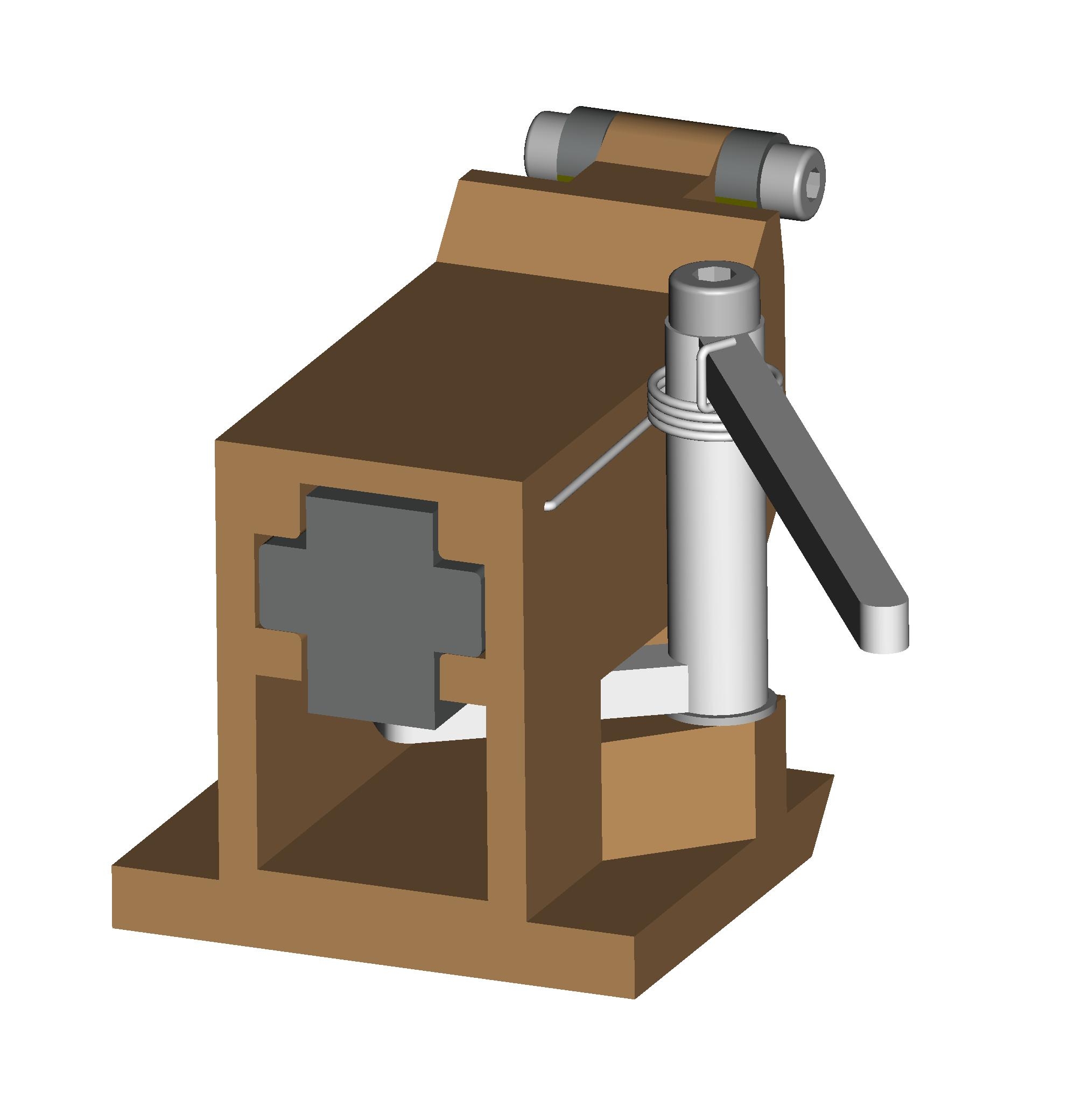
I still have my fears about the consequences of non-exact model-building and therefore will in reality have a larger stroke on the drive-rail with lift-off connection and let the closing movement be powered by a spring built into each gun-unit. See attached picture.
Thank for your interest and comments so far.
Kind regards
Bertil
- Mark as New
- Bookmark
- Subscribe
- Mute
- Subscribe to RSS Feed
- Permalink
- Notify Moderator
Very cool! ![]()
- Mark as New
- Bookmark
- Subscribe
- Mute
- Subscribe to RSS Feed
- Permalink
- Notify Moderator
What size will this be when built?
- Mark as New
- Bookmark
- Subscribe
- Mute
- Subscribe to RSS Feed
- Permalink
- Notify Moderator
The ship is the "Regalskeppet Kronan" launched 1672 and sunk 4 years later in a fight with a Danish-Dutch naval force.
She was found in 1980 by the same man who found the Vasa in 1950.
She was one of the worlds largest ships at the time and was sunk by an amateurish maneuver when the admiral turned with the wind without closing the gun ports.
(he should have had my drive-rail)
When she keeled over, fire from the cooking galley reached the gun powder storage and blew the front half of the ship away - 800 crew lost!
She was meant to carry an astonishing 125 canons of various size - the lower decks with the heavier guns.
She was just over 50 metres long and the model my brother is building will be 1:50, i.e. just over a metre.
I am helping him with a number of 3D-details and his intention is to build a sailing model, not an exact scaled down replica.
- Mark as New
- Bookmark
- Subscribe
- Mute
- Subscribe to RSS Feed
- Permalink
- Notify Moderator
You need to upload some pictures and video when it hits the water!


