Community Tip - When posting, your subject should be specific and summarize your question. Here are some additional tips on asking a great question. X
- Community
- Creo+ and Creo Parametric
- 3D Part & Assembly Design
- Changing parameter value in pattern instances in a...
- Subscribe to RSS Feed
- Mark Topic as New
- Mark Topic as Read
- Float this Topic for Current User
- Bookmark
- Subscribe
- Mute
- Printer Friendly Page
Changing parameter value in pattern instances in assembly
- Mark as New
- Bookmark
- Subscribe
- Mute
- Subscribe to RSS Feed
- Permalink
- Notify Moderator
Changing parameter value in pattern instances in assembly
Hi,
I am using creo parametric 3.0. I have to create an assembly in which I have to use a part and its pattern in a linear direction. However, I have to change the value of one parameter in all the instances.
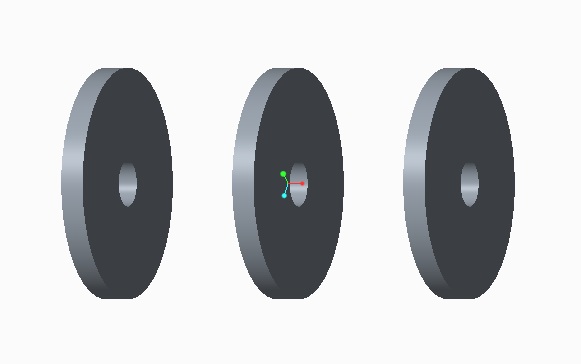
Suppose, I am going to use a disc with a hole. I want that disc patterned in a assembly with diameter of hole changing irregularly in each instance.
Whether I have to use separately named part each time, family table or something else?
Figure below is given just to show the idea.

This thread is inactive and closed by the PTC Community Management Team. If you would like to provide a reply and re-open this thread, please notify the moderator and reference the thread. You may also use "Start a topic" button to ask a new question. Please be sure to include what version of the PTC product you are using so another community member knowledgeable about your version may be able to assist.
- Labels:
-
Assembly Design
- Mark as New
- Bookmark
- Subscribe
- Mute
- Subscribe to RSS Feed
- Permalink
- Notify Moderator
Hi Nabeel,,
If you know number of hole diameters (like 20,30,40,50,60) and it fixed then go for family table and feed the values whatever you need.
but controlling the values by parameter will effect entire family table instances.
Otherwise for changing irregularly:
Create separately named parts and its parameter to drive the value irregularly.
i hope your looking the same.
- Mark as New
- Bookmark
- Subscribe
- Mute
- Subscribe to RSS Feed
- Permalink
- Notify Moderator
Hi Raj,
Thanks for your suggestion.
Actually, I am going to use that model in a simulation. After this, I would be preparing the drawings. In that case, separately named parts would be too difficult too handle if there are around ninety discs in the assembly.
I was looking for a solution which would give me flexibility to pattern all disc parts, and then I could change the inner dia of individual discs.
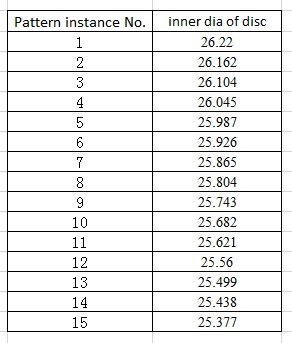
You can check a sample image below which shows variation of inner dia in pattern instances.

- Mark as New
- Bookmark
- Subscribe
- Mute
- Subscribe to RSS Feed
- Permalink
- Notify Moderator
If the instance is having a fixed value(like....instance 1=26.22) then go for family table.
- Mark as New
- Bookmark
- Subscribe
- Mute
- Subscribe to RSS Feed
- Permalink
- Notify Moderator
Hi,
Initially I am going to assign instance 1 = 26.22, instance 2 = 26.162, instance 3 = 26.104 and so on for around ninety discs. Now, during the simulation process and after every analysis result, I would be continually changing the values of dia of each and every instance.
When I use family table for changing from generic to say 2nd instance disc, creo will assign all pattern members to be using values of 2nd instance.
I have seen pattern table option when we select options for family table. Do you know about using this option?
- Mark as New
- Bookmark
- Subscribe
- Mute
- Subscribe to RSS Feed
- Permalink
- Notify Moderator
If it is for simulation try Optimization Study.
In Optimization Design, how to select one part's parameters in assembly situation?
- Mark as New
- Bookmark
- Subscribe
- Mute
- Subscribe to RSS Feed
- Permalink
- Notify Moderator
I wonder whether making a single disc as a flexible component could work; using some other geometry (maybe a sketch) in the assembly to drive the size of each disc?
No idea how flexible components would work in simulation (I'm assuming Mechanica).


