Community Tip - If community subscription notifications are filling up your inbox you can set up a daily digest and get all your notifications in a single email. X
- Community
- Creo+ and Creo Parametric
- 3D Part & Assembly Design
- Re: Cosmetic threads? Hiding threads in hidden lin...
- Subscribe to RSS Feed
- Mark Topic as New
- Mark Topic as Read
- Float this Topic for Current User
- Bookmark
- Subscribe
- Mute
- Printer Friendly Page
Cosmetic threads? Hiding threads in hidden line removed view
- Mark as New
- Bookmark
- Subscribe
- Mute
- Subscribe to RSS Feed
- Permalink
- Notify Moderator
Cosmetic threads? Hiding threads in hidden line removed view
In the model below, I have the hidden lines turned off yet you can see the threads. Are these cosmetic threads and if so (or not), how do you turn them off off when just printing the model (not a drawing)?
Thanks, Dale
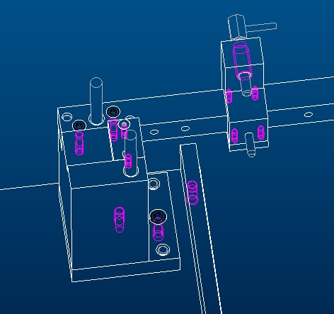
This thread is inactive and closed by the PTC Community Management Team. If you would like to provide a reply and re-open this thread, please notify the moderator and reference the thread. You may also use "Start a topic" button to ask a new question. Please be sure to include what version of the PTC product you are using so another community member knowledgeable about your version may be able to assist.
- Mark as New
- Bookmark
- Subscribe
- Mute
- Subscribe to RSS Feed
- Permalink
- Notify Moderator
In the view display properties there is a setting for hiding quilts, which is what Cosmetic threads are.
This setting is not available in section views - there is a setting when creating the section to hide quilts when the section is made.
- Mark as New
- Bookmark
- Subscribe
- Mute
- Subscribe to RSS Feed
- Permalink
- Notify Moderator
I am in WF5/Creo if that makes a difference. I do not see a setting for hiding quilts in View tab.
- Mark as New
- Bookmark
- Subscribe
- Mute
- Subscribe to RSS Feed
- Permalink
- Notify Moderator
Hello Dale,
i would think creating a layer & adding the threads to it would be the best way to manage this. That way you can have them visible on your drawing but turned off in your part. Remember to change your drawing layer status to "ignore display status of model".
John
- Mark as New
- Bookmark
- Subscribe
- Mute
- Subscribe to RSS Feed
- Permalink
- Notify Moderator
Acutally, I just was to do it temporarily for a quick print of the model for discussion. It confusses some when they don't understand what all the extra lines are.
- Mark as New
- Bookmark
- Subscribe
- Mute
- Subscribe to RSS Feed
- Permalink
- Notify Moderator
Just right clicking on the hole feature in the model tree will reveal "hide", the hole remains the cosmetic threads disappears.
- Mark as New
- Bookmark
- Subscribe
- Mute
- Subscribe to RSS Feed
- Permalink
- Notify Moderator
John,
This works good on a temporary basis, but I just realized that if I need to pick the axis of the hole I have to unhide it even though it still shows in the part.
Thanks, Dale
- Mark as New
- Bookmark
- Subscribe
- Mute
- Subscribe to RSS Feed
- Permalink
- Notify Moderator
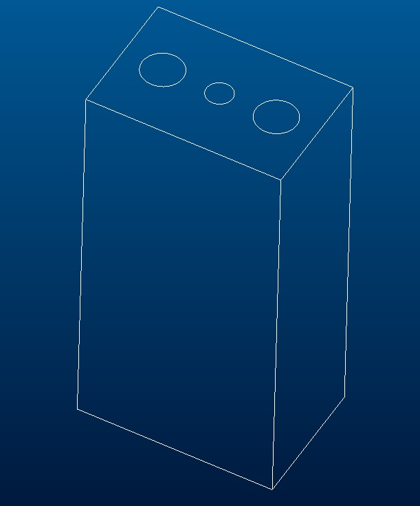
Does anyone know how not including the thread surface in the part when using the hole feature effects the parts? Right now I see a benefit in that the purple cosmetic threaded surface shown in the original question does not show up. But I want to make sure I am not opening a can of worms (i.e. a hole bunch of other problems) by doing this.
Attached are some screen shots showing how and what the results look like:
Including the thread surface:
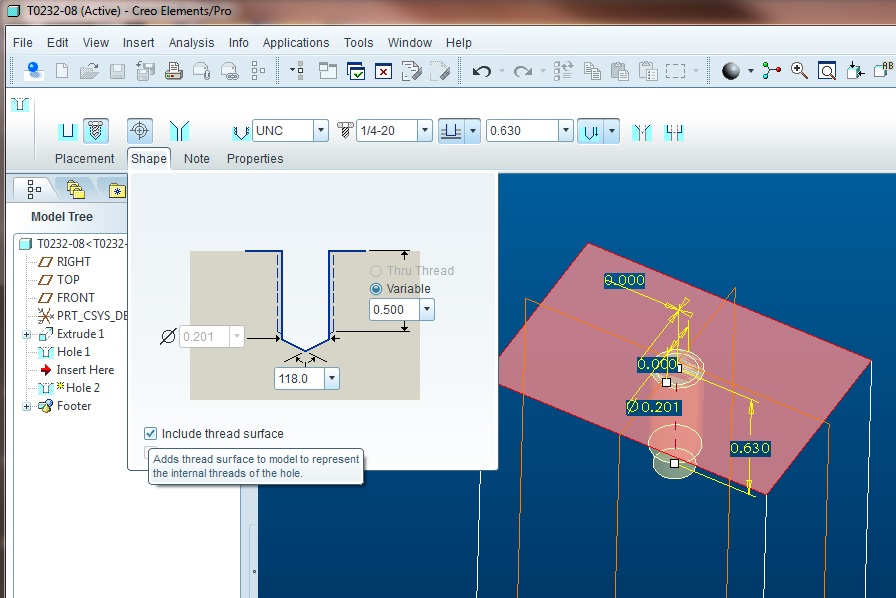
The results:
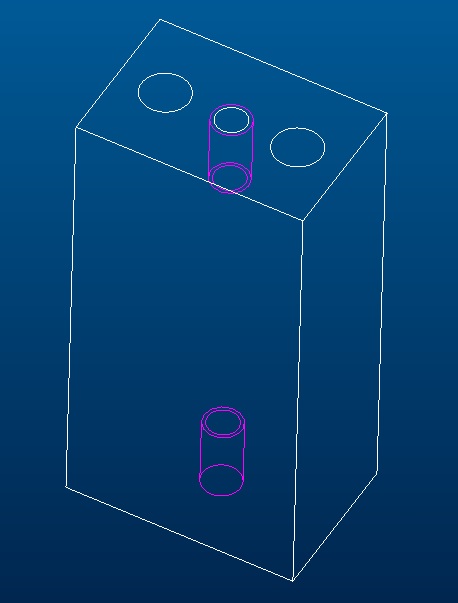
Include the thread surface unchecked.
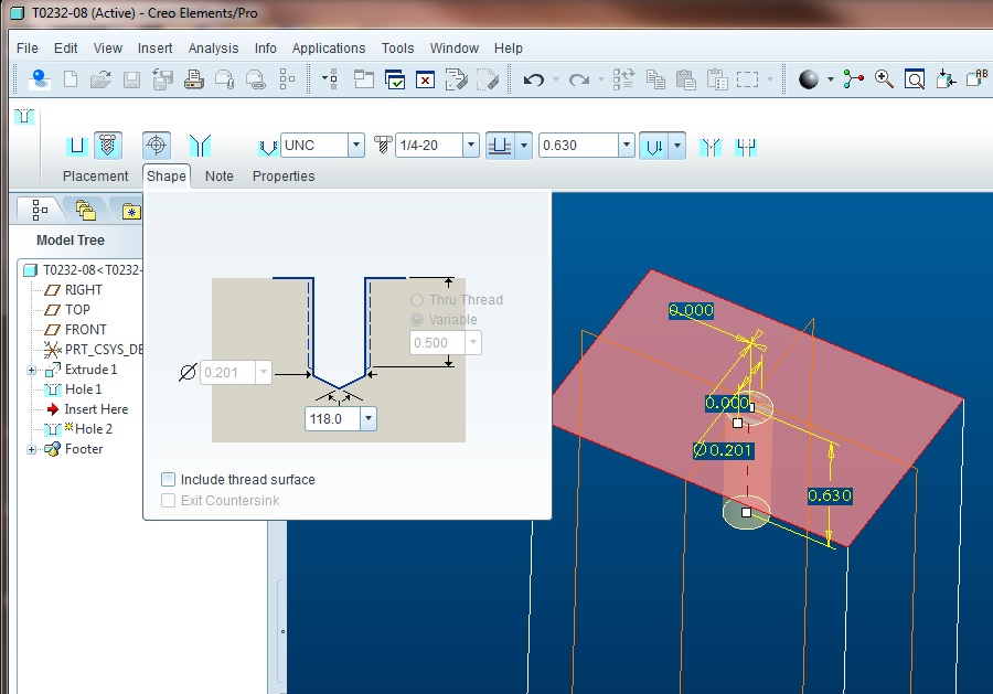
The results:
- Mark as New
- Bookmark
- Subscribe
- Mute
- Subscribe to RSS Feed
- Permalink
- Notify Moderator
Regardless of the pain these persistent features cause at other levels, I do want them available for referencing when I turn on wireframe mode. I tend to work in very tight quarters when it comes to threaded holes and the visual references to actual edges of the threads is extremely helpful.
Curious, however... if you do not show the cosmetic, do they still show up in drawings as they are suppose to?
- Mark as New
- Bookmark
- Subscribe
- Mute
- Subscribe to RSS Feed
- Permalink
- Notify Moderator
Worse than that, if you had changed the standard (default) depth of the thread (notice that I had .500), when I turned it back on, the thread depth was .482".
Yikes!!! ![]()
It did not remember that I had done this so you better not do this.
- Mark as New
- Bookmark
- Subscribe
- Mute
- Subscribe to RSS Feed
- Permalink
- Notify Moderator
I get that kind of behavior a lot when changing hole characteristics. Really poor implementation. When I change a hole from depth to through, it seems to loose all kinds of references including mating axes at next level assemblies. It really is no different than deleting and creating a new hole in many respects. I think the only thing that remains is patterns. Even then I would double check the results just in case.
- Mark as New
- Bookmark
- Subscribe
- Mute
- Subscribe to RSS Feed
- Permalink
- Notify Moderator
I think I figured out your mate issue, and it should have given me a heads up. When you are choosing surfaces to be coincident on the threaded surfaces and the bolts or what ever you are mating up. When I did this with one of these peices, it didn't know what to mate to since I must have picked the threaded surface versus the non-threaded surface when I was doing the original mates.
I am guessing that this is what you ran into. Now I am just going to have to be doubly sure what I am clicking on for those mates.
- Mark as New
- Bookmark
- Subscribe
- Mute
- Subscribe to RSS Feed
- Permalink
- Notify Moderator
Thank goodness the first part I started dimensioning - all the holes were thru/clearance holes so it didn't mess up drawings.
- Mark as New
- Bookmark
- Subscribe
- Mute
- Subscribe to RSS Feed
- Permalink
- Notify Moderator
I always reference the axis for placement (to avoid "coincidents" masking as "tangencies").
It seems the axis is also being replaced.
- Mark as New
- Bookmark
- Subscribe
- Mute
- Subscribe to RSS Feed
- Permalink
- Notify Moderator
You are correct in that it is like deleting one hole and putting in another. I am fixing my fixes from yesterday (thankfully only a few parts) but on one through threaded hole, when I unchecked "Include thread surface", today the hole was just a plain through hole with no reference (not even clearance) to a threaded hole.
- Mark as New
- Bookmark
- Subscribe
- Mute
- Subscribe to RSS Feed
- Permalink
- Notify Moderator
Holes have become more intelligent over the years, but certainly not smarter ![]()
I am not even sure how to use the automatic "clearanced" sizing for non-threaded holes. I know it is ISO based but I don't know how to invoke it.
ISO 2768 manages linear and angular dimensions and a few other features based on Fine, Medium, and Course tolerancing. Does anyone know the ISO specification that controls this hole clearance sizing in this same manner?
- Mark as New
- Bookmark
- Subscribe
- Mute
- Subscribe to RSS Feed
- Permalink
- Notify Moderator
Sorry - I thought the question was drawing views, not in the model.
- Mark as New
- Bookmark
- Subscribe
- Mute
- Subscribe to RSS Feed
- Permalink
- Notify Moderator
I have gotten in the habit of creating a HIDEME layer. Cosmetic thread is one of the features I put there.
- Mark as New
- Bookmark
- Subscribe
- Mute
- Subscribe to RSS Feed
- Permalink
- Notify Moderator
Hello,
you have to set the config option fasthlr to yes in order to hide cosmetic threads.


