
Turn on suggestions
Auto-suggest helps you quickly narrow down your search results by suggesting possible matches as you type.
Showing results for
Please log in to access translation
Turn on suggestions
Auto-suggest helps you quickly narrow down your search results by suggesting possible matches as you type.
Showing results for
Community Tip - Need to share some code when posting a question or reply? Make sure to use the "Insert code sample" menu option. Learn more! X
- Community
- Creo+ and Creo Parametric
- 3D Part & Assembly Design
- Re: Create Flat Pattern for Domed Surface with Min...
Translate the entire conversation x
Please log in to access translation
Options
- Subscribe to RSS Feed
- Mark Topic as New
- Mark Topic as Read
- Float this Topic for Current User
- Bookmark
- Subscribe
- Mute
- Printer Friendly Page
Create Flat Pattern for Domed Surface with Minimal Deformation
Mar 07, 2016
03:35 PM
- Mark as New
- Bookmark
- Subscribe
- Mute
- Subscribe to RSS Feed
- Permalink
- Notify Moderator
Please log in to access translation
Mar 07, 2016
03:35 PM
Create Flat Pattern for Domed Surface with Minimal Deformation
I have a problem that is similar to some previous threads, but I have been unable to locate a solution. I need to install a flex circuit into a semi-spherical shape and will need to play with the geometry to get the best shape for sufficient coverage and 'fit' to the surface. Realizing that I will never get a true fit to the domed surface with the flex circuit, my plan was to iterate the design by creating flat patterns of the trimmed surface but I am not able to produce the pattern I desire. My intent is to have the flat pattern 'unwrap' from the domed surface rather than project to a flat surface (as intended with formed parts). The flatten quilt feature in the model shows how it is shrinking the geometry in the flat pattern, where I would prefer it to maintain a comparable size. I have also attempted to use the Flatten-Quilt Deformation tool, but was unable to configure it properly to generate a solution.
I realize that what I'm asking for is unconventional because any flat pattern will not be able to conform to a compound curvature without some level of deformation. Once again my plan is to iterate the flat pattern design to make a physical evaluation of the imperfect fit. The flex circuit does not need to be perfectly flush with the surface so it would just be a matter of creating a geometry that did not allow too many creases or flats. I was hoping to use the all powerful Flatten-Quilt function to ease my burden of measuring/calculating the geometry, but any approaches that the community can offer will be appreciated!
Tagging some users that have commented on similar thread topics that I have found helpful in this endeavor...
This thread is inactive and closed by the PTC Community Management Team. If you would like to provide a reply and re-open this thread, please notify the moderator and reference the thread. You may also use "Start a topic" button to ask a new question. Please be sure to include what version of the PTC product you are using so another community member knowledgeable about your version may be able to assist.
Solved! Go to Solution.
ACCEPTED SOLUTION
Accepted Solutions
Mar 07, 2016
06:48 PM
- Mark as New
- Bookmark
- Subscribe
- Mute
- Subscribe to RSS Feed
- Permalink
- Notify Moderator
Please log in to access translation
Mar 07, 2016
06:48 PM
Maybe not sheetmetal if a narrow strip is already trouble for conforming to the sphere.
I am still not sure as to what kind of feature and what kind of density you are looking for.
The Octopus model seems to be the best way to consider this. Basically send out runners from a center and as they widen, add slits to further expand/conform.
Sheetmetal cannot do this reliably. Flatten Quilt will probably continue to deform although it wouldn't need to.
The best way to see how this will behave is take your best shot at the flat pattern and get an arts&crafts paper cutting printer.
That way you can see how easily it will lay into the sphere as well. Sometimes a little paper and glue will save 10's of hours in CAD.
5 REPLIES 5
Mar 07, 2016
04:07 PM
- Mark as New
- Bookmark
- Subscribe
- Mute
- Subscribe to RSS Feed
- Permalink
- Notify Moderator
Please log in to access translation
Mar 07, 2016
04:07 PM
You are out of luck on a few fronts, obviously. For one, the Kapton doesn't do domes. I would recommend doing this with the sheetmetal module. In sheetmetal, you can bend and twist but does not allow for the deformation that you are trying to avoid.
The easiest way to physically make a dome is to make it a cylinder with slits. When you push down on the upper part of the cylinder, the center where the slits are will attempt to make a dome-like shape.
The other instance you can look at is how people have carved up world maps to remove as much deformation as possible. Unfortunately, that is not a solution as you cannot have any deformation other than twist and bends.
What you are doing with this circuit is probably also as important. How robust does it have to be? Is it fully passive or are there active components installed that require rigid sections?
Regardless, there is no easy answer. No matter what, this will take some real effort on your part to come up with the right solution.
Mar 07, 2016
05:02 PM
- Mark as New
- Bookmark
- Subscribe
- Mute
- Subscribe to RSS Feed
- Permalink
- Notify Moderator
Please log in to access translation
Mar 07, 2016
05:02 PM
You have hit where I was planning on taking the design by mentioning map projections. For conception sake, take a look at the American Polyconic projection at the link below. I would like to have a main strip going along the radius of the dome with more strips coming off its side to cover as much as the dome as possible.
Map Projections: Polyconic Projections
You can see in the attached photo the first attempt that was made for the flex circuit. For this iteration the 'main strip' in the vertical orientation was too wide and created a flat spot in the dome. Otherwise this geometry was able to be placed into the dome fairly well. The dome would be approximately 8" in diameter so this would be a very large flex circuit with plenty of space to conform to such a geometry.
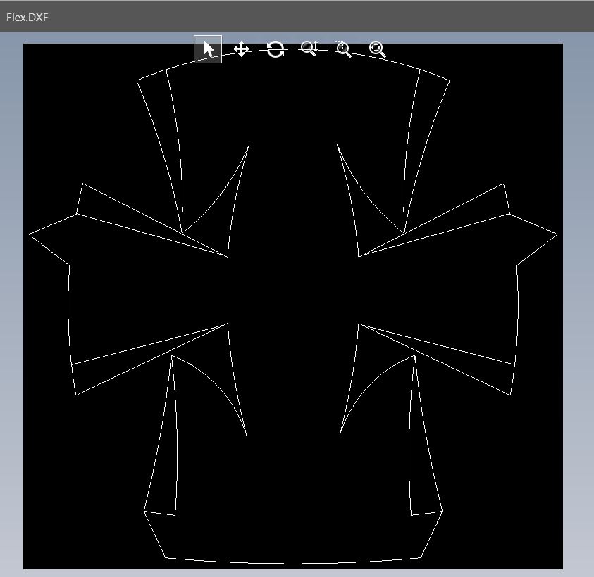
The circuit connects to a PCB which houses all the components that need rigidity so that the circuit itself can remain flexible. The flex circuit will float between two flexible thermoformed parts so its OK that it doesn't map the dome perfectly.
I hope this clarifies the question better for you. Would you still recommend the sheet metal module, or is there a way to flatten such a surface with minimal deformation similar to the map projections described?
Mar 07, 2016
06:48 PM
- Mark as New
- Bookmark
- Subscribe
- Mute
- Subscribe to RSS Feed
- Permalink
- Notify Moderator
Please log in to access translation
Mar 07, 2016
06:48 PM
Maybe not sheetmetal if a narrow strip is already trouble for conforming to the sphere.
I am still not sure as to what kind of feature and what kind of density you are looking for.
The Octopus model seems to be the best way to consider this. Basically send out runners from a center and as they widen, add slits to further expand/conform.
Sheetmetal cannot do this reliably. Flatten Quilt will probably continue to deform although it wouldn't need to.
The best way to see how this will behave is take your best shot at the flat pattern and get an arts&crafts paper cutting printer.
That way you can see how easily it will lay into the sphere as well. Sometimes a little paper and glue will save 10's of hours in CAD.
Mar 08, 2016
12:41 PM
- Mark as New
- Bookmark
- Subscribe
- Mute
- Subscribe to RSS Feed
- Permalink
- Notify Moderator
Please log in to access translation
Mar 08, 2016
12:41 PM
A DXF printout on paper and a pair of scissors should do just fine for what we are attempting. If no one else can offer a method to flatten a quilt or solid in the manner we have discussed that is exactly what I'll be doing. Thanks for your input!
Mar 08, 2016
12:50 PM
- Mark as New
- Bookmark
- Subscribe
- Mute
- Subscribe to RSS Feed
- Permalink
- Notify Moderator
Please log in to access translation
Mar 08, 2016
12:50 PM
Well, the optimum shape for your design may take on a form you hadn't seen yet in the polyconic projections.
It is hard to describe but it is somewhat fractal in nature.
The idea is that you have a few main octopi tenecals from an arc, and from the tenecals, you have runners... and optionally, more runners from those.
It will end up looking more like feathers pointing away from an open ring. That is if you require a high sensor density, for instance.
Each of the runners will conform in their own little region where the octopus arm is the spine and the runners are fillers.
Just be careful to radius all transitions generously.


